BRUCE Technical Team
Hydraulic Pile Hammer Working Principle
Hammer Principles and Selection
Hydraulic Pile Hammer Working Principle
A hydraulic pile hammer uses hydraulic power to cycle a ram and deliver repeated blows to a pile through the specified driving assembly. The hammer design controls the downstroke. Engineers assess the energy rating, impact interface, pile stress and ground response before setting the driving and acceptance criteria.Hydraulic power cycles a ram. Each blow transfers impact through the driving assembly into the pile. Check the hammer design, energy basis, interface, pile stress and project criteria.
Cycle the ramHydraulic supply, ram and model-specific downstrokeTransfer impactDriving assembly, pile-head contact and cushions where usedCheck the responseDriving stress, ground, field records and project criteria
Technical guide
Article information
Technical review policy. BRUCE prepares this reference from the cited material. Project-specific design and approval remain with the responsible project team.
Planning overview
The operator supplies hydraulic power to cycle the ram. Each impact passes through the specified driving assembly into the pile. The pile and ground respond to the resulting stress wave.
Engineers check the operating design, driving assembly and pile response together. Catalog energy, stroke or blow count alone cannot establish pile capacity.
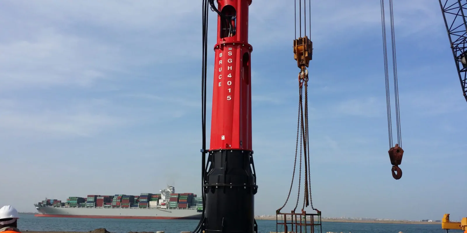
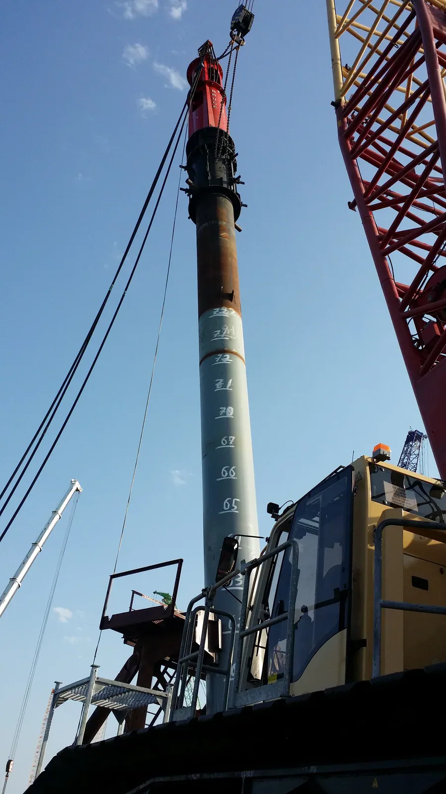
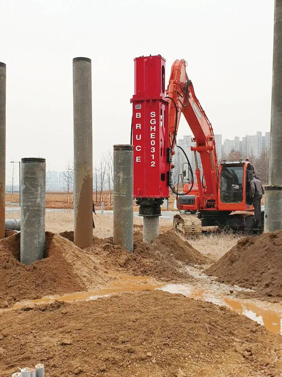
The BRUCE photographs show visible equipment and site arrangements. A photograph does not establish internal condition, transferred energy, lifting approval or pile capacity.
Impact system
Ram, driving assembly and pile
The ram delivers a blow through the driving assembly. The component arrangement depends on the hammer and pile. Use the drawing for the selected model rather than assuming one internal layout or cushion stack.
System checks
Review each part of the impact system
| Component | Function | Check before use |
|---|---|---|
| Hydraulic supply and controls | Supply and control the ram cycle | Model manual, required flow and pressure, hoses, return path, cooling, oil condition and emergency controls |
| Ram and guides | Guide the impact mass through the permitted operating cycle | Model-specific downstroke, stroke or energy setting, blow rate, alignment, condition and inspection requirements |
| Driving assembly | Transfer impact through the specified hammer-to-pile interface | Hammer and pile drawings, seating, contact, alignment, wear and component condition |
| Cushions where specified | Modify the impact pulse and protect the relevant components | Separate hammer-side and concrete-pile cushions; verify location, material, stack, condition and replacement criteria |
| Pile and ground response | The pile transmits stress waves while the ground resists movement | Allowable driving stress, ground investigation, depth and blow records, monitoring, tests and project acceptance |
Hydraulic lift and the downstroke
Hydraulic pressure raises the ram. In a single-acting design, gravity drives the downstroke. Double-acting designs add downward assistance, such as hydraulic pressure or compressed gas. Confirm the selected model’s cycle and energy basis in its manual; the SGH family name alone does not identify the internal circuit. The operator must keep the hammer within the manufacturer’s permitted stroke, energy and blow-rate range.
Rated energy and energy transferred to the pile
For a gravity-driven ram, weight multiplied by fall height gives the theoretical potential energy for the stated stroke. The manufacturer may use another rating basis for a different operating design. Rated energy is not the energy transferred into the pile. Impact velocity, hammer condition, the driving assembly, cushions where used, pile impedance and ground resistance affect transfer. Engineers can derive transferred energy from force and velocity measurements during dynamic monitoring. A monitor that calculates ram kinetic energy does not measure transferred pile energy. Confirm the measurement location and method before comparing a measured value with a catalog rating.
Driving assembly and cushions
The driving assembly connects the hammer to the pile and must fit the specified pile section. Component names and arrangements vary by hammer and project. A hammer cushion, where used, sits on the hammer side of the helmet or drive cap. A separate pile cushion between the helmet and the head of a concrete pile protects the pile and changes the impact pulse. Some hammer designs use no hammer cushion. Do not treat a hammer cushion, a product called a Drive Cap Cushion and a concrete-pile cushion as interchangeable without the manufacturer’s drawing. Check seating, contact, alignment, wear and the specified cushion replacement criteria.
Driving stress and ground response
Each blow creates a stress wave in the pile. Shaft and toe resistance affect its reflection; reflected waves can produce tensile as well as compressive stress. Excessive driving stress can damage the pile or its connections. Engineers use wave-equation analysis to assess expected driving response and stress for the selected hammer, assembly, pile and ground. The project specification defines any dynamic monitoring, restrike or load testing needed to check the installation.
Blow count and project acceptance
Record blows over a stated penetration interval together with pile ID, depth, hammer setting, interruptions and changes to the driving assembly. Blow count alone does not establish pile capacity. Ground layers, setup or relaxation, obstructions, transferred energy and pile condition can change the observed resistance. An unexpected change in penetration, loss of alignment, damaged pile head, cap movement, unstable ram cycle or monitoring threshold requires the action defined in the approved procedure. The responsible engineer must assess deviations before crews increase energy or continue outside the approved criteria.
Hydraulic supply and safe inspection
Check the required flow and pressure, hose and coupler ratings, return restrictions, cooling, oil condition and control functions for the actual equipment layout. Follow the model manual and the approved lifting and work plans. Stop and secure the system for leaks, damaged hoses, abnormal motion or sound, overheating, or another specified stop condition. Before maintenance, isolate the power source, control stored pressure and secure moving parts as the manufacturer requires. A general article cannot replace the model’s operating or maintenance procedure.
Frequently asked questions
Do all hydraulic pile hammers use a gravity-only downstroke?
Single-acting hydraulic hammers use gravity for the downstroke. Double-acting designs add downward assistance. Check the selected model’s operating cycle and rating basis in the manufacturer’s manual.
Is rated hammer energy the energy transferred to the pile?
Rated energy describes the manufacturer’s stated basis. The energy entering the pile also depends on the hammer, driving assembly, pile and ground. Engineers use the specified analysis and measurements to assess transfer.
Are hammer cushions and concrete-pile cushions the same?
They occupy different positions and perform different roles. The model and pile drawings define the required arrangement. Some hammer designs use no hammer cushion; do not substitute cushion types without approval.
Does a high blow count establish pile capacity?
Blow count requires interpretation with the hammer setting, penetration interval, pile condition and ground. The responsible engineer defines the records, analysis and tests needed for project acceptance.
Technical basis
Sources supporting the technical claims above.
Discuss Your Impact Hammer Package
Send a pile drawing and the ground information you have. Tell us your driving or testing requirements so BRUCE can review the applicable hammer and support package.