BRUCE Technical Team
Power Pack Selection
Equipment Package Planning
Power Pack Selection
Select a hydraulic power pack from the exact hammer requirements and the proposed operating duty. Confirm flow at the required pressure, then review the supply and return route, cooling, fluid, controls and site conditions. Ask the manufacturer to approve the complete configuration; engine horsepower alone cannot establish a suitable package.Match the hammer requirements to flow at pressure, hose and return layout, cooling duty, fluid, controls and site conditions.
Define demandExact hammer, circuit requirements and operating dutyReview deliveryFlow at pressure, hoses, returns and coolingConfirm the packageFluid, controls, site conditions and commissioning
Technical guide
Article information
Technical review policy. BRUCE prepares this reference from the cited material. Project-specific design and approval remain with the responsible project team.
Planning overview
The equipment supplier reviews the hammer requirements and operating conditions before recommending a power pack. The team must check the complete hydraulic route, cooling duty and controls for the proposed work.
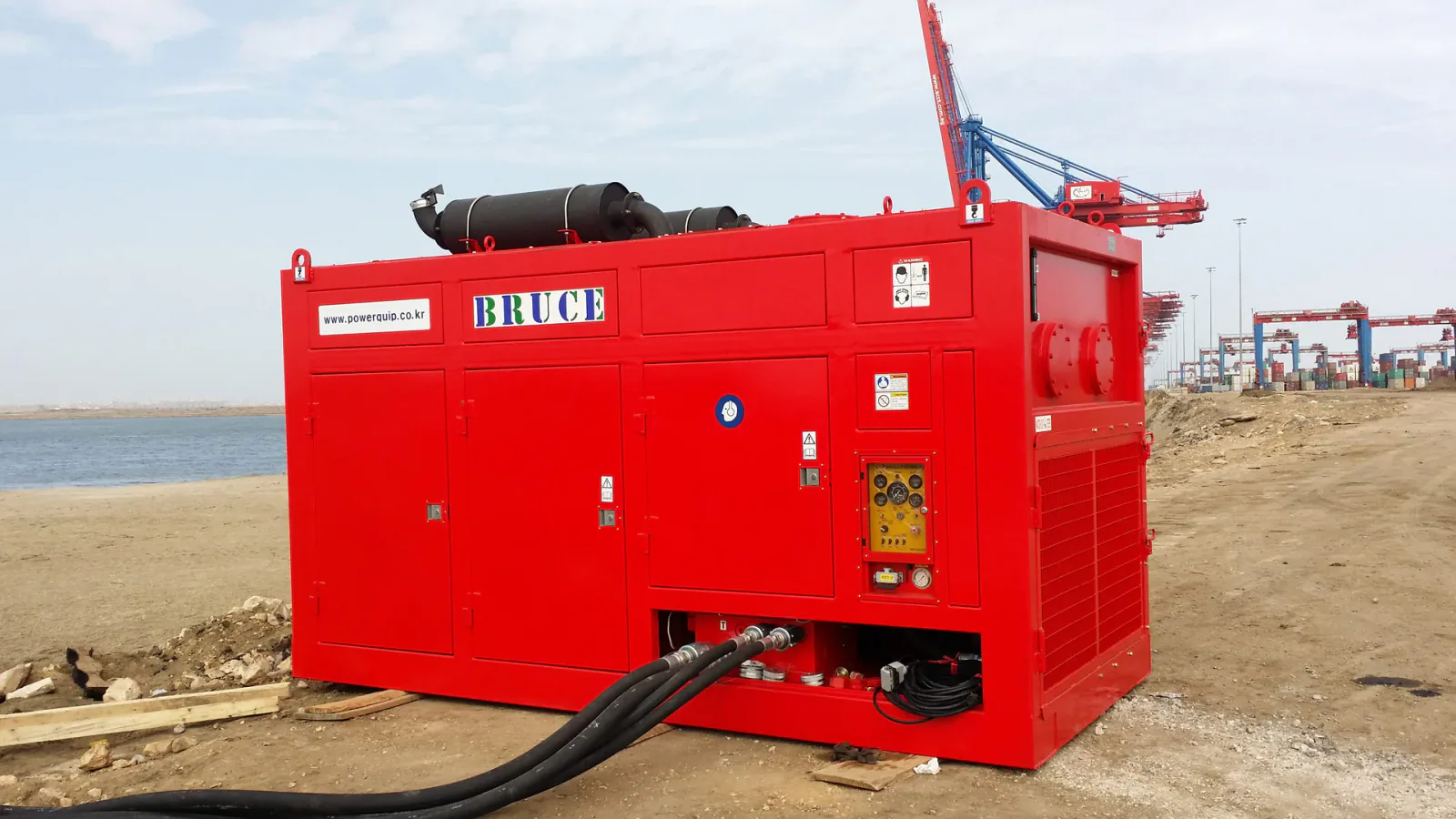
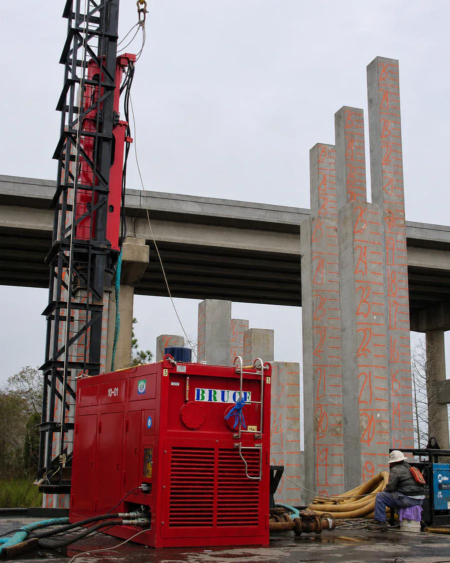
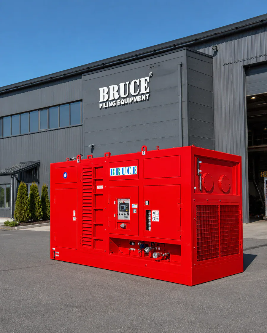
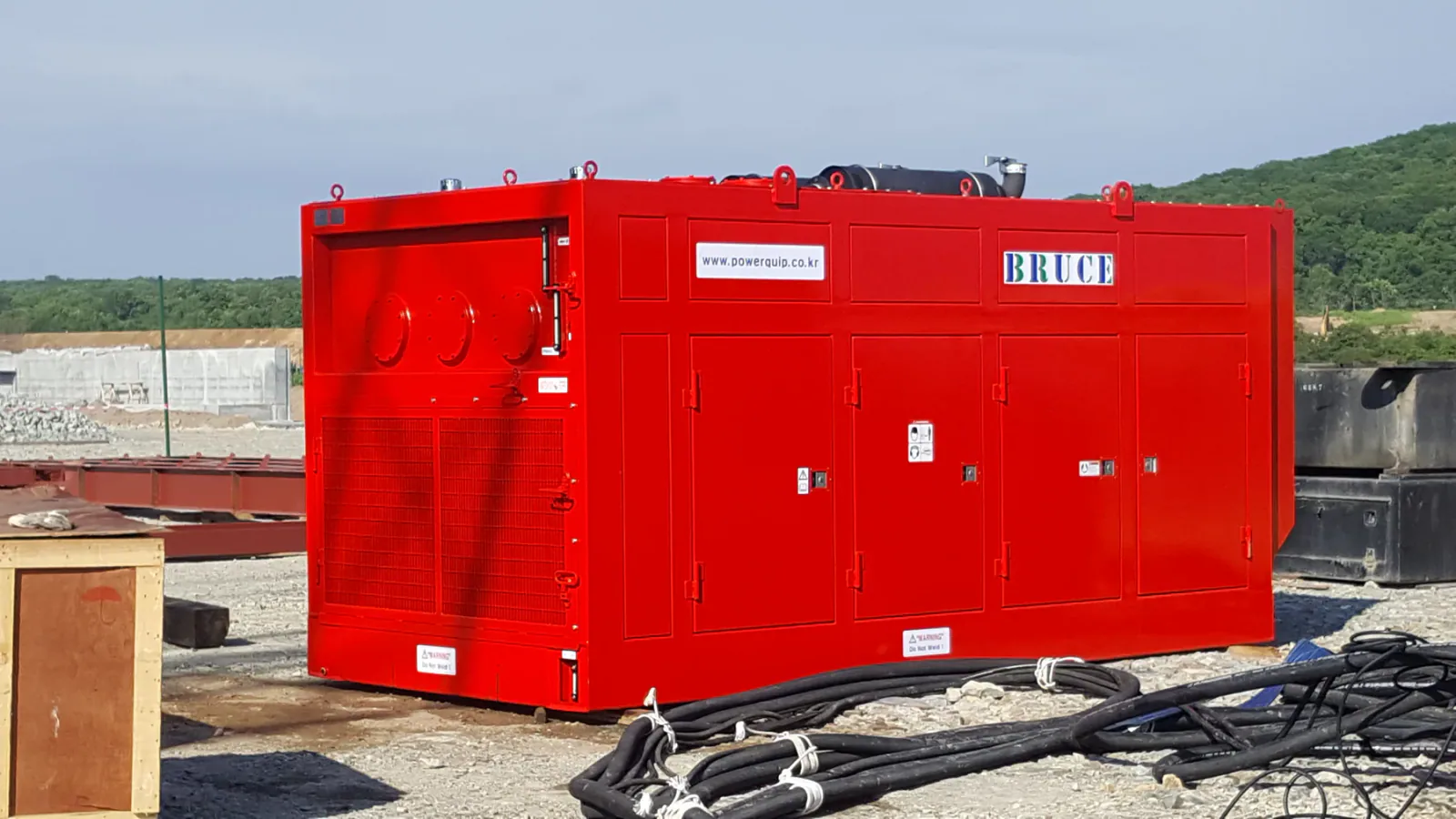
These BRUCE photographs show visible equipment and site arrangements. They do not verify internal condition, delivered flow or pressure, cooling adequacy or an approved installation.
Selection checks
Check the pack and the complete hydraulic route
Review these inputs with the equipment supplier and responsible site team.
| Review area | Information to check | Decision |
|---|---|---|
| Hammer duty | Exact model, hydraulic and control connections, simultaneous functions and operating periods | Confirm the manufacturer requirements |
| Flow at pressure | Pump capability, drive limits, circuit demand and rated duty at the same operating point | Verify the proposed pressure-flow combination |
| Hoses and returns | Length, bore, fittings, couplers, return pressure and any case drain | Approve the complete delivery and drain arrangement |
| Cooling | Heat load, ambient conditions, airflow and intended work and idle periods | Confirm the thermal basis and observation plan |
| Fluid and cleanliness | Fluid compatibility, viscosity, filtration, filling and connection procedures | Specify the manufacturer requirements and service plan |
| Controls and site | Feedback, alarms, stop functions, source supply, placement and access | Confirm compatibility and site controls |
| Commissioning | Configuration, readings, temperature trend, function tests and operating limits | Record results and assign approval for changes |
Field checks
Verify the proposed arrangement before work
Define the hammer duty before comparing power packs
Ask the hammer manufacturer for the current hydraulic and control requirements for the exact model and configuration. Record the permitted flow and pressure range, return-pressure limits, operating sequence and any separate auxiliary or drain connections. A connection drawing should identify which functions the proposed power pack supplies. The same equipment family can contain different circuit arrangements.
Describe the planned installation or extraction work, operating periods, idle periods and any functions that overlap. The supplier needs these conditions to assess pump circuits, drive demand and cooling duty. Pile and ground information helps the team define the intended work; it does not convert into a power-pack model through one pile weight or soil value.
Ask the supplier to confirm compatibility with the actual hammer and accessories.
Check flow and pressure at the same operating point
The hydraulic supplier must confirm the flow available at the pressure required for the proposed duty. A catalog maximum flow and maximum pressure may describe different operating conditions. Compare pump capability, engine or motor limits and any simultaneous circuit demand at a stated operating point. Include the permitted continuous duty and transient conditions in that review.
Keep the engine or motor rating separate from the hydraulic output available at the hammer. Pumps, controls, auxiliaries and the delivery circuit consume power or introduce losses. The nameplate engine rating alone cannot confirm the pressure and flow that the hammer receives. A relief setting limits pressure in its intended circuit; it does not prove that the pack can sustain the required flow at that pressure.
Flow and pressure affect actuator response through the actual hydraulic circuit and load. Neither provides a universal rule for hammer force, frequency, stroke or impact energy. The supplier must use the model requirements and control design when assessing those functions. Confirm the proposed settings from the manufacturer instructions rather than increasing pressure or flow to compensate for an unexplained response.
Review the hose, return and drain connections
Define the complete supply and return route before the supplier finalizes the package. Include hose bore and length, fittings, couplers, bends, changes in elevation and the oil conditions used in the calculation. Pressure loss through the route affects the pressure available at the hammer and produces heat. Check the allowed return pressure at the relevant hammer connection under the expected flow.
Some components require a separate case-drain line with its own pressure limit. Confirm the requirement, connection point and route from the exact component and system instructions. Do not assume that a case drain can share a restricted return line. The hydraulic supplier must approve changes to the return or drain arrangement.
Match hose assemblies, fittings and couplers to the fluid, pressure, temperature and movement conditions that their manufacturers specify. Plan support, bend radius, abrasion protection and routing around vehicles, lifting operations and access routes. Recheck the hydraulic calculation and installation when the team changes hose length, bore, fittings or layout. A matching connector thread alone cannot establish assembly compatibility.
Assess cooling for the proposed work and environment
The supplier must assess heat generation and heat rejection for the intended duty, ambient conditions and installation. Continuous operation, pressure losses, relief flow and restricted cooler airflow can affect the thermal balance. State the expected work and idle periods, ambient temperature, dust exposure and the available space for airflow. The required cooling arrangement depends on the actual system and conditions.
Oil temperature affects viscosity and the operating conditions of pumps, valves, seals and other components. Confirm the fluid and component temperature limits from the relevant instructions. A large reservoir or a short no-load run cannot verify cooling adequacy during prolonged work. During commissioning, monitor the temperature trend under the agreed duty and investigate alarms or a continuing rise before the team accepts the arrangement.
Keep cooler inlets, outlets and service areas accessible in the site layout. The maintenance plan should address inspection and cleaning under the actual dust or other exposure. Obtain the supplier review before changing an enclosure, cooler, airflow route or operating duty. Use the specified limits and stop procedure rather than a generic oil-temperature target.
Specify the fluid, cleanliness and service requirements
Confirm the hydraulic fluid type, viscosity requirements and compatibility with the hammer, power pack and hose assemblies. Specify the manufacturer cleanliness requirement, filtration arrangement, filter elements and the procedures for filling, flushing and connecting the equipment. Follow the approved process before mixing or replacing fluids. A viscosity grade alone does not establish that two fluids are interchangeable.
Contamination can damage hydraulic components and impair valve or control operation. Protect open connections and replacement components during transport, installation and service. Define oil sampling or condition checks where the manufacturer or maintenance plan requires them, together with filter inspection and replacement criteria.
Provide the operator with the maintenance instructions, service intervals and the required spare filters and hose assemblies. Review the actual filter indication and system condition before deciding the response. The responsible technician must investigate abnormal contamination, filter indications, leakage or deteriorating operation under the manufacturer procedure.
Confirm controls, power source and site placement
The equipment supplier must confirm the controls and feedback needed for the exact hammer and pack. Review the operator station, permitted adjustments, gauges, alarms, emergency stop and any clamp or auxiliary indications required by that arrangement. The commissioning plan should test the relevant functions and record the results. A mechanically compatible hydraulic connection does not establish control compatibility.
Ask the manufacturer whether a proposed diesel or electric drive is available and suitable for the required package. Diesel arrangements need the applicable fuel, exhaust, ventilation and emissions review. An electric proposal needs a competent electrical review of the supply, starting method, protection, isolation and cable installation. Include hydraulic and mechanical noise in the site review for an electric drive, together with the relevant equipment hazards.
Place the pack on suitable support with the clearance required for airflow, exhaust, fuel or electrical connections, inspection and maintenance. Consider hose movement, vehicle routes, spills, fire precautions and access to emergency controls. Any handling or lifting operation needs the applicable equipment instructions and lift plan. The project team must confirm the site restrictions and responsible approval before operation.
Commission the assembled system and keep the configuration record
Use the manufacturer procedure and an agreed commissioning plan for the assembled hammer, pack, hoses and controls. Competent personnel should verify the connections, permitted settings, pressure and flow where required, hammer response, oil-temperature trend, alarms and leakage. State the test conditions and measurement locations so the team can interpret the readings. One pressure reading does not verify the full operating duty.
Record the equipment identities, document revisions, hose arrangement, fluid, filter condition and commissioning results. Retain the operating and maintenance instructions and identify who can approve a change. A different hammer, hose set, control arrangement or work duty can require a new review. The operator must follow the approved range and the stated response to abnormal pressure, temperature, leakage, movement or control behavior.
Hydraulic systems can retain pressure and stored energy after the drive stops. Before inspection, disconnection or maintenance, competent personnel must isolate the equipment and release or secure stored energy under the manufacturer procedure. Never search for a pressurized leak with a hand. Treat a suspected hydraulic injection injury as a medical emergency.
BRUCE can review a candidate power pack, hose and control package from the information supplied. The responsible equipment, project and site teams retain the required hydraulic, electrical, lifting and work-plan decisions. Confirm the exact model configuration and operating documents before procurement or operation.
Frequently asked questions
Can engine horsepower select the power pack?
Engine power is one input to the review. The supplier must confirm the flow available at the required pressure, delivery losses, cooling duty and circuit compatibility for the exact hammer and operating conditions.
Can maximum flow and maximum pressure be used together?
Catalog maxima may describe different operating conditions. Ask the supplier to confirm the proposed simultaneous pressure-flow point, drive limits and permitted duty. A relief setting alone does not verify sustained flow at that pressure.
Does a larger reservoir prevent overheating?
Reservoir size alone cannot confirm cooling adequacy. The supplier must assess heat generation, heat rejection, ambient conditions, airflow and operating duty. Use the agreed commissioning procedure and component limits to evaluate the temperature trend.
What should I send for a power-pack review?
Start with the hammer model or datasheet, expected hose length and a site photo. Describe the work periods, site conditions and available fuel or electrical supply. BRUCE can identify the additional information needed for a candidate package.
Technical basis
Sources supporting the technical claims above.
Discuss Your Power Pack Package
Send the hammer model or datasheet, expected hose length and a site photo. Tell us the operating duty and available power source so BRUCE can review a candidate package.