United States Vibro Hammer Specification Guide – Sheet, Casing, H-Pile
JH KIM
view : 279
BRUCE Piling Equipment · Technical specification guide
Read the ratings, then check the complete pile-driving system
Vibro hammer specifications describe different parts of a system: the force generated by the vibrator, its movement, the hydraulic supply, the pile connection and the extraction limit. A large centrifugal-force figure alone does not establish which hammer will install your pile.
This guide helps U.S. contractors read a data sheet and prepare a review for sheet piles, casing and H-piles. For published BRUCE ratings, start with the SGV model specifications.
What the main vibro hammer ratings actually tell you
Read the column heading, units and configuration note together. In particular, distinguish a published maximum from the operating value proposed for your project.
Scroll sideways on smaller screens to read the complete comparison.
| Rating | Meaning | Question to resolve |
|---|---|---|
| Eccentric moment kg·m | The rotating mass–offset measure used to calculate excitation force. | Is it fixed or adjustable, and what moment applies to the proposed operating condition? |
| Centrifugal force kN or lbf | The cyclic excitation-force rating at a stated speed. | At what frequency is it rated? Keep it separate from clamp force and extraction line pull. |
| Frequency vpm or Hz | Vibration cycles per minute or per second; 1,800 vpm equals 30 Hz. | What is the available operating range with the specified power source? |
| Amplitude mm or in | The stated displacement of a defined vibrating assembly. | Is it single or peak-to-peak amplitude? Does the rating include the clamp, the pile, or neither? |
| Pressure and flow bar / psi; L/min / US gpm | The hydraulic conditions specified for the hammer. | Which values are required operating conditions, and which are equipment limits? |
| Extraction line pull kN or lbf | The manufacturer’s stated pull limit for extraction. | What limits also apply to the clamp, suspension, rigging and carrier in the proposed arrangement? |
Catalog example: BRUCE lists the SGV-300 at 34 kg·m eccentric moment, 1,120 kN centrifugal force and 1,730 vpm maximum frequency. Its amplitude entry is explicitly labeled “including universal clamp.” Confirm the applicable configuration before comparing that value with another data sheet.
Keep mass, force and moment separate. Specify mass in kg or lb, force in kN or lbf, and eccentric moment in kg·m. A bare “ton” value can be ambiguous in an international quotation. Request the manufacturer’s stated unit convention rather than converting an unlabeled number.
Why frequency changes the force figure
For a simple model of peak cyclic excitation force, F = Me × (2πf)2, with force F in newtons, eccentric moment Me in kg·m and frequency f in Hz. This relationship is described by Massarsch, Fellenius and Bodare in their research on vibratory pile driving (PDF, Eq. 1).
Illustrative calculation · not a BRUCE model rating
Assume a fixed eccentric moment of 30 kg·m.
At 30 Hz
≈ 1,066 kN
30 × (2π × 30)2 ÷ 1,000
At 27 Hz
≈ 863 kN
30 × (2π × 27)2 ÷ 1,000
A 10% reduction in frequency gives a 19% reduction in calculated force at the same eccentric moment: (27 ÷ 30)2 = 0.81.
This explains why two force figures need their associated operating speeds. It does not predict penetration rate, pile capacity or an approved operating setting. The real hammer–pile–soil response requires a separate review.
The same research distinguishes single amplitude from peak-to-peak amplitude and includes the clamp and pile in the moving mass. A catalog’s free-vibration amplitude should therefore not be presented as a measured movement of the pile in soil.
Change the specification brief when the pile changes
A common hammer family can use different accessories. Confirm the actual contact geometry and approved attachment arrangement, not just the name of the pile type.
Sheet piles
Profile and handling arrangement
Identify the section designation, gripping location and whether sheets will be handled singly or in pairs. Include interlock condition, guides and the installation sequence in the method review. Ask for the proposed jaw arrangement to be shown on the profile drawing.
Casing
Diameter, wall and clamp layout
Provide outside diameter, wall thickness, length, open- or closed-end condition and any internal contents. Ask for a drawing showing the beam, clamps and permitted diameter range. Confirm the weight of the complete vibrating assembly for that layout.
H-piles
Section details and grip position
Supply the section designation, flange and web dimensions, length and intended gripping surface. Have the supplier confirm jaw engagement and attachment suitability. Include any splices or handling restrictions that affect the installation plan.
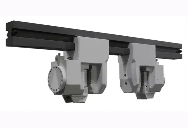
BRUCE’s vibratory hammer features page describes double-clamp arrangements for casing and other profile options. A photograph shows an arrangement; an approved dimensional drawing establishes whether it fits your pile.
Check the power source as part of the specification
For a crane-suspended package, identify the proposed power pack, hose arrangement and controls. For an excavator attachment, give the exact machine model and auxiliary-circuit information rather than relying only on excavator weight.
- Ask for the operating requirement: the pressure and flow needed for the intended duty, with the manufacturer’s permitted limits clearly separated.
- Show the full circuit: proposed hose lengths and connections, return-path arrangement, cooling and any required case-drain connection.
- Resolve unit conventions: specify US gpm rather than an unspecified gallon unit. Identify the measurement location and operating condition for supplied hydraulic data.
For carrier information, use the excavator-mounted vibratory hammer guide. Keep the carrier review with the model recommendation so the quoted hammer and available machine can be assessed together.
Complete the review with ground data and a verification plan
Send the full ground profile, available borehole or CPT records, groundwater information, pile drawings and target depth. An isolated SPT number or a fixed force-to-pile-weight multiplier does not describe every layer, toe condition or obstruction.
The FHWA driven-pile manual, Volume II discusses vibratory installation and its limitations. Have the project team establish the installation method, any trial or monitoring requirement, and the acceptance criteria for the completed foundation.
Record what a trial is intended to establish. Useful information includes pile identification, installation depth versus time, equipment configuration, operating observations and the specified vibration measurements. Keep measured results separate from the catalog ratings and define the response to unexpected ground conditions before work starts.
Specification questions
Is the hammer with the highest centrifugal force always the right one?
Compare force together with frequency, eccentric moment, assembly mass, pile connection, hydraulic supply and ground conditions. A larger force rating does not settle carrier compatibility, drivability or site vibration performance.
Does vibration isolation at the suspension prove nearby buildings are protected?
No. Isolation within the equipment and ground vibration at a neighboring structure are different questions. Use the project’s assessment and monitoring requirements for the actual ground, distances and structures.
Can a catalog specification be submitted as the complete installation method?
The data sheet identifies equipment characteristics. The installation submission also needs the proposed configuration, ground and pile information, handling arrangements and project-specific review. Ask the project team to define the required documents.
Sources and scope
Published by BRUCE Piling Equipment. Product figures are drawn from the linked BRUCE specification and features pages. The force example is an illustrative calculation using the cited research relationship; it is not a field test or a recommended operating setting.
Additional reading: PDCA, Basic Principles of Hammers for Sheet Pile Installation (PDF). Use the project’s governing specifications and the selected equipment documentation for the final review.
Send drawings with your inquiry
Request a BRUCE vibro hammer specification review
Include the pile profile and length, clamp arrangement, ground report, carrier or power source, U.S. project location, required date and extraction requirements. Identify any missing information so the recommendation can state its assumptions clearly.