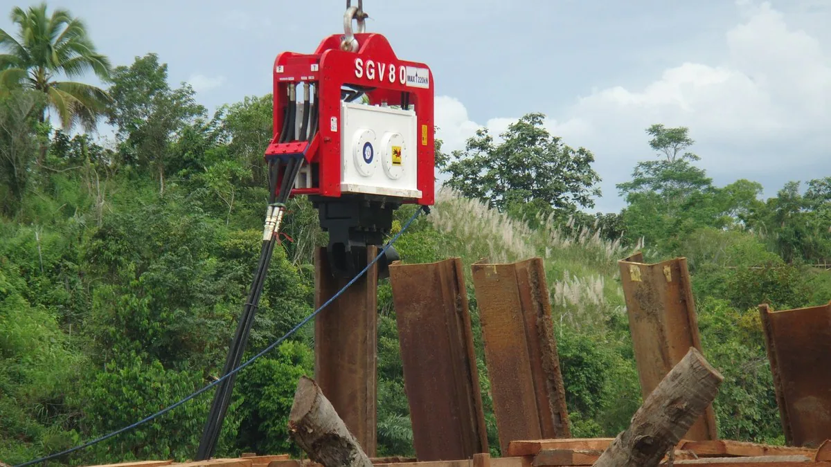
BRUCE SGV80 vibratory hammer with steel profiles at a worksite

Knowledge CenterPile Types

H-Beam Pile Guide

Review an H-pile’s section drawing, design role and ground profile before choosing the installation equipment. Confirm the steel and splice details, driving limits and acceptance requirements, then check the clamp or drive cap, hydraulic supply and crane arrangement for the approved sequence.

Review the section and driving plan

Direct answer

What is a steel H-pile?

A steel H-pile has two flanges joined by a web. Designers specify the section for its foundation or retaining duty and check the loads, ground response and installation stresses. Some specifications identify rolled HP sections; other H or fabricated sections need project approval. A building beam designation alone does not approve a section for pile driving.

Last updated
Prepared byBRUCE Technical Team
ScopeSteel section and driving review

The SGV80 photographs show equipment and steel profiles. Use the section drawing to confirm H-pile geometry.

Check the section and installation requirements

Section requirements and installation checks
Planning item Requirement to review Installation checks
Section and material Depth, flange width, web and flange thickness, steel grade and condition affect structural behavior and the driving interface. Use the specified section drawing and material records. Check straightness, damage, tolerances and the proposed clamp or driving-head contact.
Foundation or retaining role A bearing pile and a soldier pile supporting excavation lagging can have different load paths and construction stages. Confirm axial, uplift and lateral duties where applicable. Keep the foundation or retaining design, support stages and pile-head connection with the installation plan.
Ground and toe conditions Shaft and toe resistance depend on the ground and design. A boulder, buried object or sloping hard surface can deflect or damage a pile. Review the investigation along the pile length. Agree on toe details, driveability assumptions, stop conditions and approved responses to unexpected resistance.
Hammer and driving arrangement Clamp fit, impact head protection, alignment and the hammer-pile system affect the section during installation. Check equipment limits and pile stresses for the proposed sequence. Review guides, hydraulic supply, crane duty and any nearby structure or vibration limits.
Splices and service requirements Long piles may need splices. Permanent piles need durability provisions; temporary piles may need a separate extraction plan. Use approved splice details and inspection requirements. Confirm corrosion protection, cutoff and connection work, or assess removal loads and ground effects before extraction.

References: 1, 2, 3, 4, 5

01

Specify the section and its load path

Use the section properties and steel grade from the project specification and the applicable section standard. Check the dimensions on the drawing against the delivered material. The designer must approve any substitute section, splice or change in steel grade before installation.

For a foundation pile, the geotechnical design assesses shaft and toe resistance for the required loads. The structural design checks the section, unsupported length, bending and connections. Ground conditions and the pile’s role determine how much resistance the design assigns to the shaft or toe.

A soldier pile in a retaining system also needs the specified lagging, supports, embedment and excavation sequence. Confirm that retaining duty separately from any axial foundation role. Keep changes in temporary support and exposure with the construction plan.
References: 1, 4

02

Assess the hammer, pile and ground together

A vibratory hammer transfers cyclic force through its clamp. Vibratory installation or extraction can suit a compatible steel section where the ground and project requirements permit it. Check jaw contact, flange dimensions, clearance and alignment against the equipment supplier’s drawings and limits. A clamp family name cannot confirm the fit of a particular section.

For impact driving, review the hammer, driving head or cap, pile and ground as a system. Wave equation analysis can estimate blow counts and driving stresses for the assumed equipment and resistance profile. Check those assumptions, the proposed operating range and pile-head protection before approving the sequence.

Dense layers, coarse particles, buried structures or rock contact can create hard driving or toe damage. More impact energy or a larger vibratory hammer cannot guarantee passage through an obstruction. Follow the agreed stop and review procedure if penetration changes, the pile loses alignment or damage is suspected.

References: 2, 3

03

Detail the head, toe and splices before driving

The engineer may specify a toe reinforcement or shoe for the expected driving and bearing conditions. Use the approved detail and installation procedure. A shoe does not establish the bearing layer or guarantee that the pile can pass an isolated boulder without damage.

Splices must transfer the forces required by the design and installation. Use the approved welded or mechanical detail, check alignment and follow the specified welding procedure, inspection and acceptance requirements. The project team must resolve a damaged or misaligned splice before driving continues.

Review the head condition and driving interface during installation. Keep the impact head or drive cap centered and check cushions where the specified arrangement requires them. After driving, complete the cutoff and pile-head connection under the design details, including any required coating repairs.

References: 2, 3

04

Compare the driving record with the acceptance plan

Before production, define the driving criteria, pile stress limits, minimum penetration where required and stop conditions. Record pile identification, position, depth, alignment, hammer settings, penetration or blows, interruptions, splices and observed damage. Compare unexpected resistance with the investigation and nearby pile records before changing the method.

A high blow count or an unexpected stop alone cannot establish the required capacity. Driving can change the soil around a pile, and resistance can increase through setup or decrease through relaxation. The responsible engineer defines any waiting period, restrike, dynamic measurements or static load tests used for acceptance.

Predrilling or jetting can change the resistance available to the completed pile. Use those aids only within approved limits and keep their records with the pile installation record. The designer must assess their effect on capacity and the acceptance requirements.

References: 1, 2, 3

05

Plan permanent service or temporary removal

For permanent piles, the designer sets durability provisions for the exposure and design life. These may include a corrosion allowance, coating or another protection system. Check the specified inspection and repairs at handling points, clamp contact, splices and cutoff areas.

For temporary piles, confirm that removal is permitted at the proposed construction stage. Assess extraction resistance and the effect on adjacent foundations, utilities and remaining supports. Pile self-weight alone does not describe the forces involved in pulling an embedded section.

Check the extraction method, hammer and clamp limits, lifting connections and crane configuration with the responsible project team and suppliers. Include the working radius, estimated forces and agreed stop conditions. BRUCE can review SGV vibratory or SGH hydraulic impact equipment for the approved installation sequence; the project team retains design, lifting, monitoring and acceptance duties.

References: 1, 2, 5

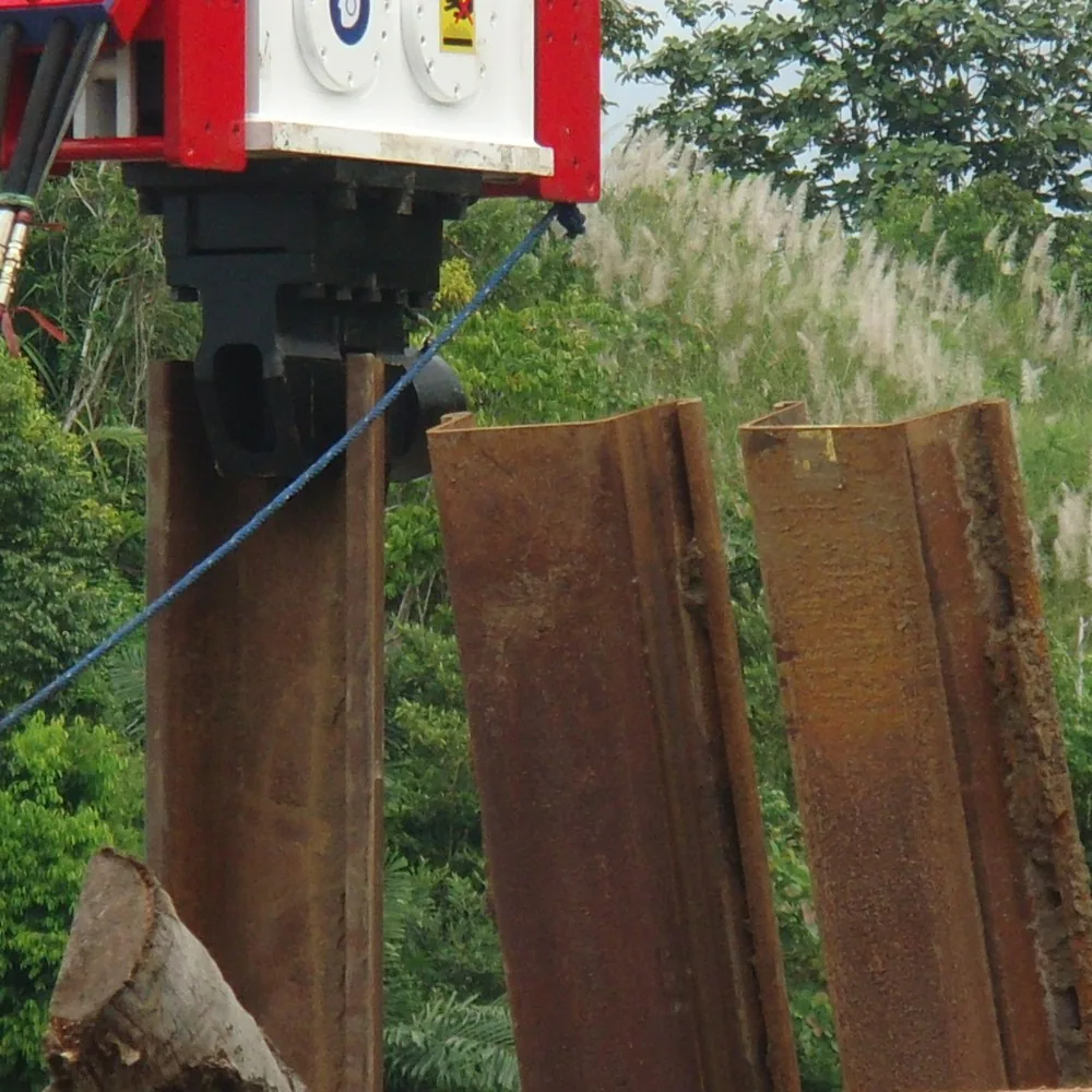
Close view of BRUCE SGV80 clamp area and steel profiles at a worksite
BRUCE SGV80 clamp area, hydraulic hoses and exposed steel profiles.

Equipment review

Discuss the H-pile equipment arrangement

Send the H-pile section drawing and ground information you have. The BRUCE Technical Team can review equipment options for the approved installation or extraction sequence.

Discuss your project

Frequently asked questions

Can an ordinary H-beam replace a specified steel H-pile?

A substitute needs the designer’s approval. Compare the section properties, steel grade, structural demand and installation stresses with the specified pile. Confirm the splice, head and toe details and the equipment interface before using it.

Does a universal clamp fit every H-pile section?

Check the actual clamp drawing and supplier limits against the section dimensions, jaw contact and clearances. Include the pile length and weight, alignment and any extraction demand. The clamp name alone cannot confirm that fit.

Does refusal prove that an H-pile has reached its required capacity?

An unexpected stop can reflect an obstruction, damage, equipment performance or resistant ground. Record the event and follow the project’s review procedure. The responsible engineer applies the specified termination and acceptance criteria.

Can the crane load for extraction use only the pile weight?

The extraction plan must also assess resistance from the ground and the equipment arrangement. Check estimated forces, crane and manufacturer limits, lifting connections and nearby ground effects before pulling the pile.