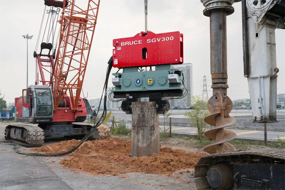
BRUCE SGV300 vibratory hammer on a steel tubular pile beside a crane and drilling equipment

Knowledge CenterSoil and Ground Conditions

Soil Conditions and Hammer Selection

Review the ground profile with the pile drawing and installation requirements before comparing hammers. The same soil name can describe layers with different density, strength and drainage. Include the depth and thickness of resistant layers, groundwater observations and nearby structures in the equipment review.

Review soil and method checks

Direct answer

How do soil conditions affect hammer selection?

Engineers assess the hammer, pile and ground as one installation system. Soil descriptions help frame that assessment, but they cannot specify a hammer model or prove that a pile will reach the required depth. Check driveability, pile stresses, site limits and the project’s acceptance requirements before confirming the equipment package.

Last updated
Prepared byBRUCE Technical Team
ScopeGround profile and equipment review

The BRUCE photographs show visible equipment arrangements. Use the ground investigation and installation records to assess soil conditions and performance.

Review the ground before comparing hammers

Ground evidence and installation checks
Ground condition Response to review Checks for the method
Sand and gravel Density, grading, fines and layer thickness can change penetration resistance. Coarse particles may obstruct a pile. Review the investigation and pile geometry. Consider vibratory driving for a compatible pile where the ground and site limits permit it; check dense layers and obstruction risk before relying on that method.
Clay and fine-grained soils Strength, stress history and drainage affect installation resistance. Driving can disturb the soil, and resistance can change with time. Review strength data and the expected installation response. Assess the proposed vibratory or impact sequence, pile stresses and any specified restrike or load testing.
Layered or cemented ground A pile can pass one layer and meet a much more resistant layer below it. Review the full profile to the required depth. Assess driveability through resistant zones and agree on stop conditions and approved method changes.
Cobbles, buried material or rockhead Local contact can stop or deflect a pile and cause damage. An unexpected stop does not identify the material at the toe. Compare the event with investigation and nearby piles. The engineer must assess the obstruction and approve any removal, drilling or foundation change before work continues.
Groundwater and sensitive surroundings Water pressure and drainage affect ground response. Pile installation can also cause vibration or ground movement near structures and utilities. Review dated water observations, construction stages and site sensitivity. Agree on monitoring, limits and actions with the project team before installation.

References: 1, 2, 3

01

Read the profile with the investigation limits

Use boring logs, samples and test records to describe the ground along the pile length. Note layer boundaries, fill, coarse particles and any evidence of buried structures. Check the investigation depth and spacing against the pile locations. A borehole or sounding describes one location and may miss an isolated obstruction.

Read SPT results with the test procedure and penetration record. An incomplete test is not a completed N-value. Check any energy or overburden corrections used in the interpretation. CPT and CPTu provide profiles that need interpretation and correlation with the ground investigation; a resistance peak alone cannot select a hammer or identify rockhead.

Keep dated groundwater levels and piezometer heads with their datum and observation depth. A CPTu test records pore pressure at its filter location during penetration. Interpret that pressure with the drainage and test conditions before using it to assess groundwater. Ask the geotechnical engineer which conditions to use for construction and whether pumping or seasonal changes need review.
References: 1, 2

02

Check the proposed vibratory stage

A vibratory hammer transmits cyclic force through a clamp into the pile. Contractors use vibratory driving for compatible steel profiles, including sheet piles and tubular piles, where the ground and project requirements permit it. Favorable granular ground can suit this method, but density, fines, layering and pile geometry affect the response.

Clay strength and sensitivity, dense zones, coarse particles and obstructions can limit penetration. Review the proposed frequency and force with the hammer supplier, pile details and site restrictions. A larger hammer cannot guarantee passage through an obstruction. If the pile stalls or moves out of alignment, follow the agreed stop and review procedure.

In susceptible saturated granular ground, cyclic loading can generate excess pore pressure and reduce effective stress. The project engineer must assess the relevant ground response and nearby assets. Saturation alone does not establish liquefaction susceptibility, and a worksite photograph cannot confirm the subsurface conditions.

References: 2, 3

03

Assess impact driving as a hammer-pile system

An impact hammer delivers repeated blows through the driving interface. Engineers review the hammer, helmet or drive cap, cushions where required, pile and ground together. Wave equation analysis can estimate driving stresses and blow counts for the assumed system and resistance profile. Check the input assumptions and the proposed operating range before approving the driving plan.

High rated energy alone does not establish suitability. Excessive driving stresses can damage a pile, and contact with a boulder or buried concrete can deflect or damage the toe. Review hammer performance, alignment and pile condition if driving differs from the plan. Hard layers or rockhead may require an approved toe detail, drilling or another foundation method.

A project may use vibratory installation followed by impact driving where the design and specification permit that sequence. Define the changeover, stress limits and acceptance checks before production. Do not assume that reaching depth or recording a high blow count proves the required capacity.

References: 2, 3

04

Review method changes and site limits

Predrilling or jetting can reduce driving resistance and change the soil resistance available to the completed pile. The engineer must review that effect, set the permitted limits and define the acceptance checks. Consider bore support, groundwater and spoil or water handling where the chosen aid requires them. Some projects require a different installation method or foundation arrangement.

Assess nearby structures, utilities and any sensitive operations before installation. Agree on vibration or movement monitoring, trigger levels and the response to an exceedance. Select controls for the actual site; a soil label or hammer type cannot establish a universal safe distance or vibration level.

BRUCE can review SGV vibratory and SGH hydraulic impact equipment for the approved sequence. Include the pile drawing and ground investigation, then check the clamp or driving interface, hydraulic supply and crane capacity at the working radius. The responsible project team retains design, lifting, monitoring and acceptance duties.

References: 2, 3

05

Confirm the plan through installation records

Use test piles or a trial sequence where the project requires them to compare the predicted and observed response. Record pile position and depth, the ground profile, hammer settings, penetration or blow counts, alignment and any damage or interruption. Keep records of drilling, jetting and other approved changes with the pile record.

Driving changes the soil around the pile. Resistance may increase through setup or decrease through relaxation, depending on the soil and installation conditions. The engineer must define any waiting period, restrike, dynamic measurements or static load tests used for acceptance. Review unexpected results before applying the same settings to production piles.

References: 2, 3

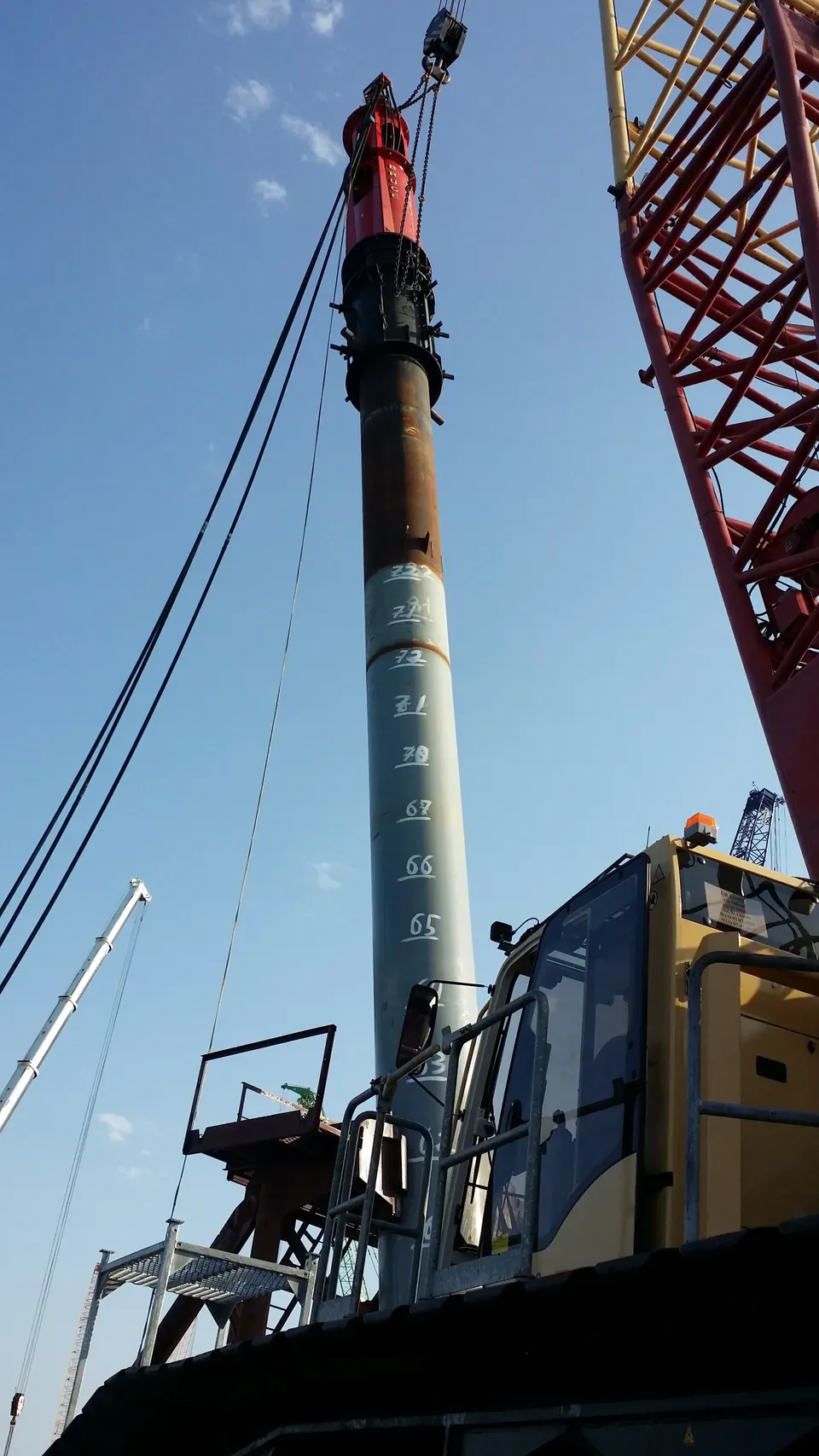
BRUCE hydraulic impact pile hammer positioned on a steel tubular pile beside a crane
BRUCE hydraulic impact hammer on a steel tubular pile. The photograph shows the driving arrangement and crane; use the project records to assess the ground and installation results.

Equipment review

Discuss equipment for the approved sequence

Send the pile drawing and ground investigation you have. The BRUCE Technical Team can review equipment options for the approved installation sequence.

Discuss your project

Frequently asked questions

Can an SPT N-value specify a hammer model?

No. Review the test quality and interpretation with the full ground profile, pile geometry and installation requirements. Engineers assess the proposed hammer-pile system and acceptance plan; one N-value cannot provide that assessment.

Is a vibratory hammer suitable for all sand or gravel?

No. Density, fines, coarse particles, layering and pile geometry affect penetration. Check the ground investigation, equipment limits and site restrictions. Dense zones or obstructions may require review of the method.

Does a higher impact energy solve hard driving?

Increasing energy can increase pile stresses without resolving the cause of hard driving. Follow the approved driving limits and review hammer performance, pile condition and the ground evidence before changing the settings or method.

How should the team confirm capacity after installation?

Follow the project’s design and acceptance requirements. The responsible engineer defines the driving criteria and any restrike, dynamic measurements or static load tests. Depth or penetration resistance alone does not establish the required capacity.