BRUCE Technical Team
Groundwater and Pile Driving
Soil and Ground Conditions
Groundwater and Pile Driving
Read dated groundwater observations alongside the soil layers and pile geometry. Water pressure and drainage can change driving resistance during installation and afterward. Review the expected response, site controls and acceptance criteria before choosing a method.
Water observationsLevel or head, depth, datum and dateGround responseDrainage, resistance and movementField checksAgreed triggers and acceptance records
Technical guide
Article information
Technical review policy. BRUCE prepares this reference from the cited material. Project-specific design and approval remain with the responsible project team.
Planning overview
Use the observation date, datum and depth to compare groundwater readings with the ground investigation. Ask the project engineer which water levels and pressures to use for construction.
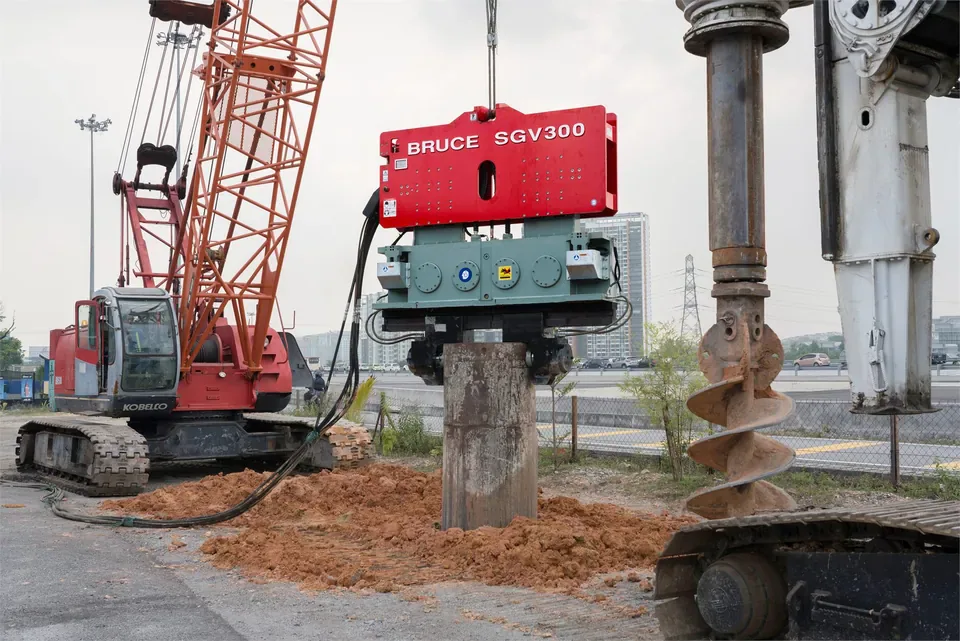
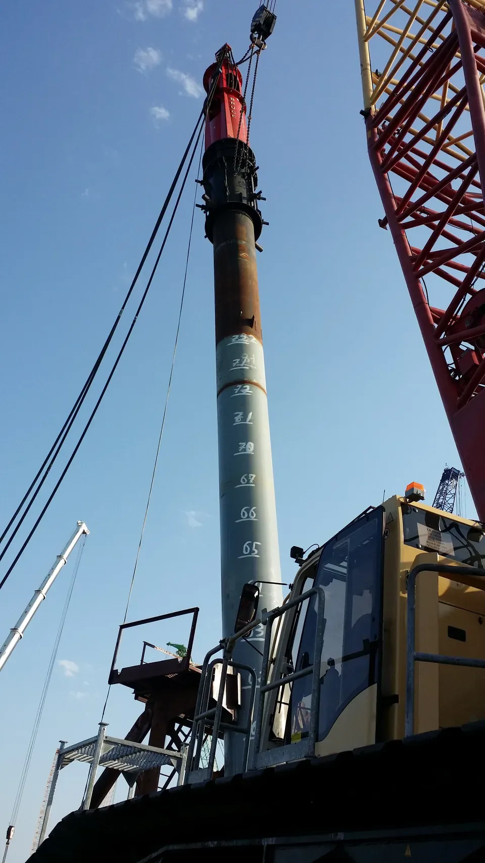
The BRUCE worksite photos show equipment arrangements. Use the project investigation for groundwater conditions and the approved method for installation.
Ground investigation
Compare water observations and field records
Compare readings against the soil layers and work sequence. Each instrument describes a location, depth and time.
Records to check
| Record | What it captures | Check before use |
|---|---|---|
| Borehole water observation | Entry or level, date, time after drilling and datum | Check drilling-water effects and whether the level had time to equilibrate. |
| Piezometer readings | Head for the stated interval and changes with time | Review the isolated depth and compare tidal, seasonal or pumping influences where relevant. |
| CPTu pressure and dissipation | Pressure response at a specified filter and during a test pause | Check filter location, saturation and test procedure. Cross-check with samples and groundwater instruments. |
| Dewatering records | Pump operation, water levels and any measured movement | Compare measured drawdown and movement against the approved limits. |
| Pile installation records | Pile depth, blow count or penetration rate, settings and condition | Check any hold, restrike or load testing requirements before acceptance. |
Bring the ground profile to the work plan
Check the target layer, pile geometry and planned monitoring before reviewing the candidate equipment.
Read water levels and pressures by depth
A water-table elevation describes the free water surface in an unconfined aquifer. A piezometer measures hydraulic head for its screened or isolated interval. A confined layer can have head above the top of the layer. Perched water can lie above the regional water table. Record the instrument, response interval, datum, date and time with each reading. Drilling water and slow equilibration can distort a borehole reading. Use repeat observations where rainfall, seasons, tides or pumping may change conditions.
Read the boring logs, soil samples and SPT records alongside the water observations. CPT records cone resistance and sleeve friction. CPTu adds pore pressure at a stated filter position. Pressure measured while the probe advances reflects the penetration response as well as the ground condition. Use the filter location and saturation record, and review any dissipation hold. Use groundwater instruments and the site investigation to establish design groundwater conditions.
Effective stress during and after driving
In saturated soil, effective normal stress equals total normal stress minus pore-water pressure. At the same total stress, a rise in pore pressure lowers effective stress. A reduction in pore pressure from drawdown can increase effective stress under comparable total stress and cause compressible layers to settle. Displacement driving can generate positive excess pore pressure in saturated clay. Soil disturbance and displacement can also contribute to remolding and heave.
The pressure response depends on the soil, drainage and the pile. Resistance can increase after driving as pressures dissipate and the soil recovers. Engineers call this increase setup. In some dense silts and fine sands, resistance can decrease with time, a response called relaxation. Use the project’s testing schedule and acceptance criteria when reviewing resistance after driving.
Vibratory driving, impact driving and ground response
Vibration can reduce resistance at the pile-soil interface in suitable conditions. A fast penetration rate alone does not establish liquefaction. Loose saturated sands and some low-plasticity silts can lose strength if cyclic loading builds enough excess pore pressure. Assess susceptibility and cyclic demand using the site investigation. Check the potential for ground movement near foundations, utilities and slopes. Impact driving can also generate excess pore pressure.
Compare candidate vibratory or impact equipment using the pile section, target depth, soil profile, permitted method and site limits. For impact work, review predicted blow counts and pile stresses against the approved driving criteria. Check the hammer and pile interface, crane capacity at working radius, and the hydraulic supply and hose route where applicable.
Plan pumping, casing and installation aids
Start with the source of inflow and the pressure in each relevant layer. Where excavation or predrilling calls for water control, have the responsible engineer assess the working platform, bore support, seepage and uplift. Check whether temporary casing or an engineered water-control system is required. Review potential settlement outside the work area before pumping and follow applicable discharge requirements.
If pumping changes groundwater levels around the piles, have the engineer check pile resistance during pumping and after groundwater recovers. Treat jetting and predrilling as installation aids. Either can change shaft or toe resistance. Use them only where the project permits them and the engineer has checked their effect on the pile and its acceptance criteria.
Measure the response and apply acceptance criteria
Before production, agree on monitoring locations, baseline readings, trigger levels and who can stop work. The site team may use piezometers, settlement points or vibration monitors according to the risks. Record inflow, heave, movement, pile condition, driving settings and penetration or blow counts as required. If a trigger is reached, follow the agreed pause and review procedure.
Confirm the specified depth, installation records and acceptance checks. Use restrike, dynamic measurements or static load tests where the project calls for them. A blow count or penetration rate alone cannot establish capacity. The responsible engineer decides whether the work meets the project criteria.
Frequently asked questions
Which water reading belongs in the ground profile?
Record the method, response depth, date and datum. Use repeated readings and the soil profile to distinguish a water table from perched water or head in a confined layer.
Can a rapid vibratory drive prove liquefaction?
Assess the soil’s susceptibility and the expected cyclic loading. A rapid drive alone gives no measure of excess pore pressure or loss of effective stress.
Can dewatering affect nearby foundations?
Drawdown can increase effective stress in compressible layers and lead to settlement. Have the project engineer review the drawdown limits, monitoring and discharge controls before pumping.
Does reaching depth prove pile capacity?
Follow the specified installation and acceptance procedure. The project may require blow records, measured driving stresses, a restrike or load testing.
Technical basis
Sources supporting the technical claims above.
- FHWA GEC-5, Geotechnical Site Characterization
- FHWA GEC-12, Design and Construction of Driven Pile Foundations, Volume I
- FHWA GEC-12, Design and Construction of Driven Pile Foundations, Volume II
- FHWA Central Artery / Tunnel Project, Chapter 3: Construction Equipment and Methods
- Caltrans Geotechnical Manual, Groundwater, September 2025
Review your site and pile details
Send the ground report, dated water observations, pile drawing and target depth. Include the planned water controls and field limits. BRUCE can review candidate equipment with the project team.