BRUCE Technical Team
SPT, CPT, N-Value Basics
Soil and Ground Conditions
SPT, CPT, N-Value Basics
SPT records the blows needed to advance a sampler at selected depths. CPT records cone resistance and sleeve friction as a probe advances. CPTu adds pore pressure. Use the logs and samples to interpret the ground profile before reviewing pile driveability.
SPTBlows and penetration at a test depthCPT and CPTuResistance and friction profiles, plus pressure for CPTuDriveabilityGround profile, pile details and field criteria
Technical guide
Article information
Technical review policy. BRUCE prepares this reference from the cited material. Project-specific design and approval remain with the responsible project team.
Planning overview
Read the raw logs with the field procedure and correction record. Match test depths to the project ground profile before using a correlation.
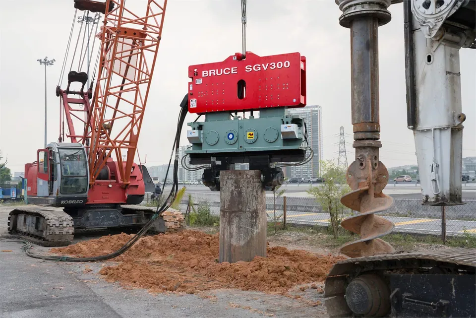
The hero photograph shows a BRUCE SGV300 vibratory hammer at a piling worksite. The photograph provides equipment context. Use the project investigation for ground conditions and test results.
Ground investigation
Compare the field records
Keep the measurements, their correction basis and the engineering interpretation separate in the project file.
SPT, CPT and CPTu
| Review item | SPT | CPT and CPTu |
|---|---|---|
| Test coverage | Discrete intervals in a borehole | Near-continuous profile during the push |
| Field measurements | Blows and penetration for each drive increment | Cone resistance qc and sleeve friction fs. CPTu adds pore pressure at the specified filter. |
| Sample evidence | Split-barrel sampler may recover a disturbed sample | Use borehole samples for material classification |
| Quality checks | Drive intervals, hammer energy, rods, borehole and sampler | Calibration, zero checks, depth datum and pore pressure filter saturation where applicable |
| Termination | Record blows and actual penetration when a drive stops short | Record depth and termination notes. Investigate coarse material, hard ground or obstructions using other evidence. |
From the ground profile to the field plan
Check resistance changes against test locations, sample descriptions and groundwater readings. Use the project records to confirm the assumed driving response.
Read the SPT drive record
For a completed standard penetration test, the technician drives a split-barrel sampler in three nominal 150 mm increments. The first increment seats the sampler. Add the blows from the next two increments to get the field N-value for the final 300 mm. If the test stops early, read the actual blows and distance advanced. Keep a partial drive separate from a completed N-value. Look at the borehole log and any disturbed sample from the test interval.
A high count or refusal may come from dense soil, a coarse particle, an obstruction or other site or test conditions. Use the samples, drilling notes and nearby investigation points to assess the cause and the layer’s extent. One refusal entry cannot confirm continuous rock or establish a pile-driving refusal limit.
Check the correction basis
The hammer’s delivered energy affects the blow count. N60 puts the count on a reference energy ratio of 60 percent. Depending on the adopted correlation, the procedure may also account for rod length, borehole diameter and sampler configuration. Keep the field count, the correction method and its inputs in the record so another engineer can trace the value.
Where the selected method calls for effective overburden normalization, it uses (N1)60. Check which quantity the correlation requires before comparing values. A correction cannot remove local geology or sampling limits.
Read CPT and CPTu channels by depth
A cone penetration test pushes an instrumented probe at a controlled rate. The probe records cone resistance qc and sleeve friction fs. A piezocone test, or CPTu, also measures pore pressure. u2 denotes a measurement at the cone shoulder, just behind the tip. Check the reported filter location and saturation record when interpreting the pressure channel. Where the unequal-area correction applies, qt denotes cone resistance corrected for pore pressure acting on the cone’s unequal end areas. Keep qc and qt distinct.
Use sleeve friction and any friction ratio or normalized index with the calculation convention in the report. Dissipation data, where available, can help assess pore pressure response and drainage. The near-continuous profile can flag changes between spaced SPT intervals. Cone response can blur thin layers, and gravel, cobbles, obstructions or hard ground can stop a push. CPT yields no soil sample. Compare the interpreted soil behavior with borehole samples, laboratory classification and groundwater observations.
Compare the logs on the same datum
Check the test locations, depth references and ground elevations before lining up profiles. Compare a rise in resistance with the soil description, sample recovery and any drilling or push termination notes. If the logs conflict or coverage is thin, flag the interval for geotechnical review. The responsible engineer can specify more investigation or an approved contingency before production driving.
Check driveability and field acceptance
Combine the interpreted profile with the pile type, toe, length, target depth, groundwater and site restrictions. No single N-value, cone resistance or pore pressure reading sizes a hammer or establishes pile capacity. For impact driving, a wave equation analysis can estimate blow count and driving stresses for the assumed hammer, pile, cushion and soil resistance. Review vibration limits, access and the full equipment package with the project team.
Compare installation records with the approved procedure as work proceeds. Record depth, operating settings, penetration or blow counts, pile condition and any required monitoring. The responsible engineer specifies any trial, restrike, dynamic or static testing and the applicable acceptance criteria. Stop and obtain review if driving or monitoring reaches a project limit.
Frequently asked questions
Can I compare field N with N60?
Check the quantity required by the adopted correlation. Record the field blow count and the energy and other correction inputs used for N60. Keep any effective overburden normalization separate.
Does CPT measure pore pressure?
CPTu adds a pore pressure channel to the cone resistance and sleeve friction measurements. Check the filter position. The label u2 applies to a filter at the cone shoulder, just behind the tip.
Does refusal identify rock?
Use the termination notes, actual advancement, samples and other investigation points to assess why the test stopped. A coarse particle, an obstruction or hard ground can interrupt a test.
What information should I send for equipment review?
Send the ground report with the field logs and any correction notes, plus the pile drawing, target depth, crane setup, site limits and acceptance requirements. Flag missing records so the project team can follow up.
Technical basis
Sources supporting the technical claims above.
- FHWA Geotechnical Aspects of Pavements, Chapter 4
- FHWA GEC-5, Geotechnical Site Characterization
- Caltrans Cone Penetration Test design parameters, September 2023
- FHWA GEC-12, Design and Construction of Driven Pile Foundations, Volume I
- FHWA GEC-12, Design and Construction of Driven Pile Foundations, Volume II
Discuss your investigation and pile details
Send the ground report, pile drawing and target depth. BRUCE can review candidate equipment and identify the details still needed.