BRUCE Technical Team
Pile Types and Equipment Matching
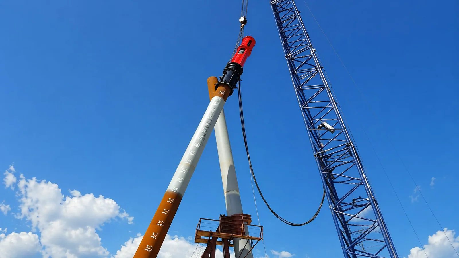
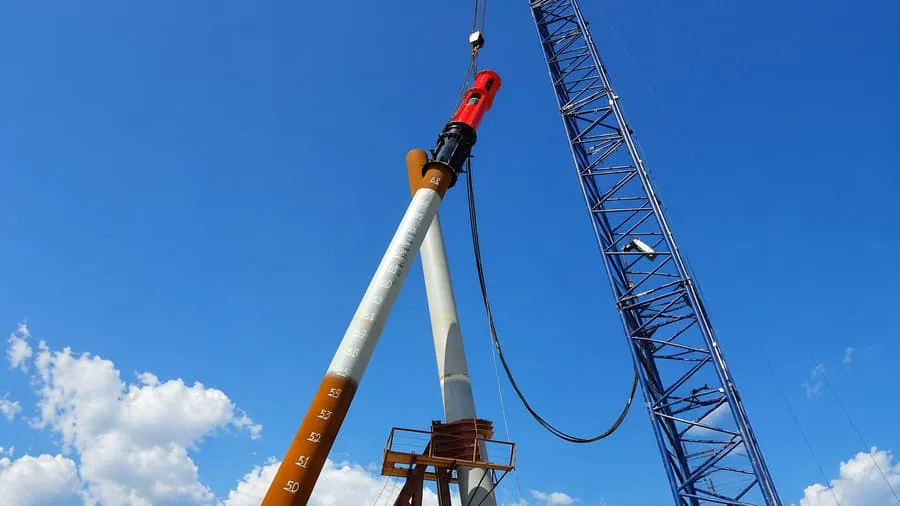
Pile Types
Pile Types and Equipment Matching
Match piling equipment to the actual pile drawing and intended work. Check the section, material, ground conditions, installation or extraction method, clamp or driving head, crane and hydraulic package. The project team defines the required field records and acceptance criteria. Include them in the manufacturer’s review of a candidate hammer and its operating limits.Use the pile drawing, intended work and ground conditions to review the method, clamp or driving head, crane, hydraulics and acceptance requirements.
Define the pileDrawing, material, section and intended functionReview the methodGround, driving or extraction and site limitsConfirm the packageInterface, handling, hydraulics and acceptance
Technical guide
Article information
Technical review policy. BRUCE prepares this reference from the cited material. Project-specific design and approval remain with the responsible project team.
Planning overview
Start with the pile’s dimensions and function. The same pile family can need different equipment when the ground, depth, permitted method, extraction duty or acceptance requirements change.
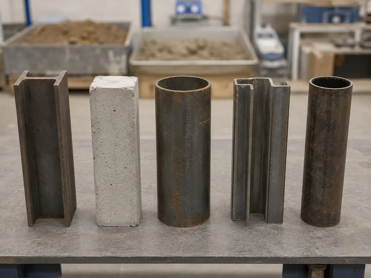
The pile-section image illustrates geometry. It is not a project drawing or material certificate and cannot verify dimensions, interface fit or an approved installation method.
Pile and equipment review
Review the pile family and the actual drawing
Use these checks with the project specification and manufacturer instructions.
| Pile family | Details to check | Method and interface review |
|---|---|---|
| Steel sheet piles | Section, length, interlocks, coating, condition and wall alignment | Review permitted driving or extraction methods, exact clamp contact and guide arrangements. |
| Steel H-piles | Section designation, flange and web dimensions, grade, splices and orientation | Check jaw or driving-head contact, alignment and driving stresses for the selected method. |
| Steel pipe piles | Diameter, wall thickness, toe, open or closed end, splices, mass and pile-head condition | Review plugging and ground response with the proposed clamp or driving head, method and acceptance basis. |
| Casing and drive tubes | Bore-support or structural role, diameter, wall, shoe, joints and temporary or permanent use | Coordinate installation and any extraction with the drilling or concrete sequence, interface and handling limits. |
| Precast concrete piles | Section, concrete strength, reinforcement or prestress, head, toe, splices and condition | Review the approved installation method, driving-head alignment, applicable cushions and allowable driving stresses. |
Field checks
Confirm the arrangement before work
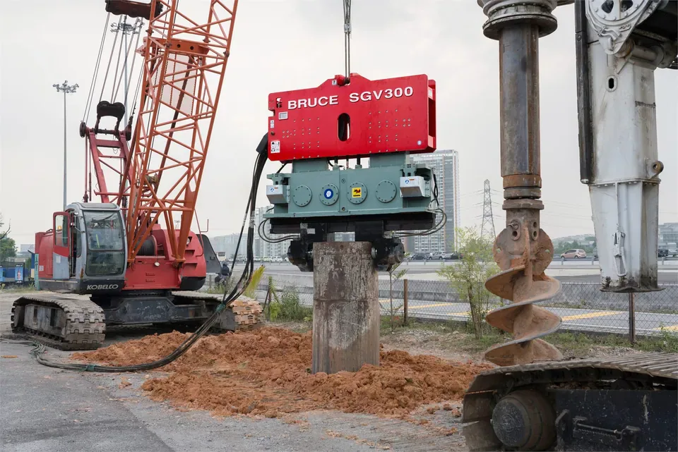
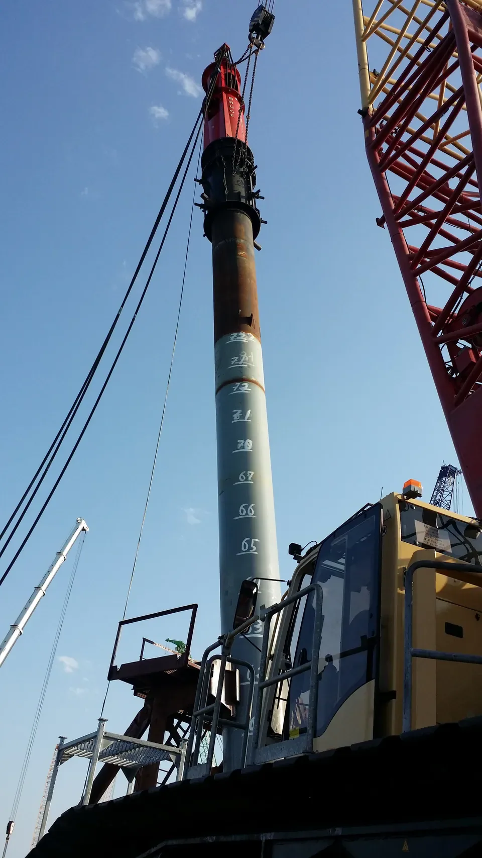
Start with the pile drawing and required function
The project team must identify whether the pile supports structural loads, retains ground, supports a bore or serves another temporary or permanent function. State the installation sequence, target depth, design loads where relevant, extraction or reuse requirement and the governing specification. A temporary casing and a structural pipe pile can have similar outside dimensions but different work and acceptance requirements.
Record the material, section, wall or flange and web dimensions, length, mass, toe, joints, splices, coating, condition and any inclination. Include the drawing tolerances and contact locations. The equipment supplier and pile designer must check the proposed clamp or driving-head arrangement against those details; a family name or nominal diameter cannot establish fit.
Review the soil layers, groundwater, dense or stiff zones, fill, obstructions and investigation uncertainty. These inputs affect resistance, pile response and the choice of installation or assistance method. The responsible engineers must review any predrilling, jetting or method change for its effect on pile performance and the acceptance basis.
Steel sheet piles
For steel sheet piles, check the actual section and interlock details, pile length, coating and condition. The wall layout, guides, installation sequence and alignment requirements also affect the equipment arrangement. Select the jaws and gripping position from the manufacturer’s approved configuration; an attachment used on another sheet profile may not fit.
Vibratory driving and extraction can be reviewed where the pile, ground and project limits permit. Impact driving, press-in, predrilling or another approved sequence may be needed for the site. Do not infer penetration rate, extractability or compliance with noise and vibration limits from the pile profile alone.
Define checks for interlock engagement, alignment, pile damage, movement and the required installation or extraction records. The responsible team must assess abnormal resistance or wall movement before changing the driving method or operating limits.
H-piles and steel pipe piles
For H-piles, confirm the section designation, flange and web dimensions, orientation, steel grade and splice details. Check the clamp faces or driving head against the actual section and the permitted load direction. The handling and driving review must address alignment, unsupported length and the applicable buckling and driving-stress limits.
For steel pipe piles, add outside diameter, wall thickness, ovality, toe and pile-head details, splices and pile mass. Open-ended and closed-ended piles displace ground in different ways. Soil plugging can affect the response of an open-ended pile, so the designer and installation team must consider it in the driveability and acceptance review.
Vibratory, impact, combined or other permitted methods depend on the pile, ground and project requirements. Structural use alone does not prescribe an impact finish or a particular test. The project specification and responsible engineer define the installation records, tests and acceptance criteria. A penetration or blow record must be interpreted under that agreed basis.
Casing installation and extraction
Identify what the casing does before choosing the installation equipment. It may support a bore during drilling, remain as part of the foundation or serve another specified construction role. Check diameter, wall thickness, shoe, joints, grip area, condition and the selected installation system. Vibratory, impact, rotary or other casing methods require different equipment and work arrangements.
Where casing will be extracted, coordinate the sequence and timing with excavation, groundwater control, reinforcement and concrete placement as applicable. The responsible designer and construction team must address bore stability and concrete integrity under the approved procedure. Installation success does not establish that extraction will be feasible.
Review the casing condition, embedment, ground resistance, any time-dependent change and uncertainty about release. Check the complete load path, component ratings and handling arrangement for extraction. Clamping pressure, gripping force and static line pull describe different quantities. Use a crane for extraction only where its manufacturer permits that intended use, including any vibratory duty. Stop and assess a stuck casing before increasing pull or changing the method.
Precast concrete piles
Use the pile drawing and material specification to confirm the section, concrete strength, reinforcement or prestress, head and toe details, splices and condition. The pile designer and equipment supplier must review the proposed installation method and handling arrangement. Do not assume a vibratory clamp or driving head approved for steel also suits concrete.
For impact driving, confirm the complete head assembly, contact area, alignment and the specified cushion arrangement. A hammer cushion, where the hammer design uses one, and a pile cushion at the pile head, where specified, have different positions and duties. Use the model and assembly instructions to establish which components apply, their materials and dimensions, and the inspection and replacement criteria.
The driving analysis must address the applicable compression and tension stresses, including easy-driving conditions. Inspect the pile head and specified cushions during work. Cracking, spalling, crushing, eccentric contact or other agreed stop conditions require assessment before driving resumes. Changes to the hammer, head assembly or cushions may require another fit and stress review.
Match handling, hydraulics and the working arrangement
Confirm the complete load path through the pile, clamp or driving head, hammer, rigging and support equipment. Cap, helmet, drive-cap and insert terminology can vary between assemblies; identify each part from its drawing and function.
A clamp’s grip rating cannot establish lifting capacity. The lifting team must check the actual supported load in each phase, designated lifting points, crane instructions and load-chart deductions at the planned radius and configuration.
The supplier must confirm flow at the required pressure, cooling duty, fluid, controls, connections, and return or drain limits for the exact hammer package. Plan hose movement, routing, support, clearance and access. Review guides, leaders or templates with the pile length and inclination. Waterborne work also needs review of the vessel or platform, water depth, current, weather, access and applicable environmental restrictions.
Before inspection, adjustment or disconnection, competent personnel must isolate equipment and release or secure stored energy under the manufacturer’s procedure. Keep personnel clear of suspended loads. Lower, support and secure components before inspection access.
Plan field checks and acceptance
Agree the required records before work: pile identity, equipment and accessory configuration, installation sequence, depth, alignment, pile condition and the operating or test records specified for the method. Where a trial is required, use its results to review the proposed arrangement and the agreed assumptions. Another site’s photograph or driving record cannot approve the current pile system.
Define stop criteria and the review needed after unexpected resistance, slip, deformation, cracking, movement, abnormal equipment response or a proposed method change. Temporary work may also need removal and reuse records. The responsible engineer must interpret the required installation and testing evidence; equipment ratings and operating records alone do not establish foundation capacity or acceptance.
BRUCE can review a candidate SGV vibratory or SGH hydraulic impact package from the pile drawings and intended duty. The responsible project and lifting teams retain the required design, work-plan, lifting, monitoring, permit, testing and acceptance decisions.
Frequently asked questions
Does the pile family determine the hammer model?
Use the exact pile drawing, ground profile, intended method and project requirements. Piles in the same family can have different dimensions, interfaces, handling loads and acceptance criteria. The manufacturer must confirm the candidate equipment and its operating limits.
Does a pipe pile’s diameter confirm clamp fit?
Diameter is one input. The supplier must also review wall thickness, ovality, contact position, coatings, condition, component combination and the intended loads. A stated diameter range or grip rating cannot establish approval for driving, extraction or lifting.
Do structural piles require an impact finish?
The project specification and responsible engineer determine the permitted installation method and acceptance evidence. Structural use alone does not require an impact finish. Review any combined sequence, driving records and tests against the agreed project basis.
What should I send for a pile and equipment review?
Start with the pile drawing, intended work, ground report and a site photo. State the target depth, permitted method, extraction requirement and acceptance criteria. BRUCE can identify the additional interface, crane and hydraulic information needed for a candidate package.
Technical basis
Sources supporting the technical claims above.
- FHWA GEC-12, Design and Construction of Driven Pile Foundations, Volume I
- FHWA GEC-12, Design and Construction of Driven Pile Foundations, Volume II
- FHWA-NHI-18-024, Drilled Shafts: Construction Procedures and LRFD Design Methods
- HSE INDG291, Providing and using work equipment safely
- HSE, Planning and organising lifting operations
- California OSHA, Section 1600 Pile Driving
- DGUV Rule 101-604, Section 3.7 Civil engineering work: piling and extraction
Discuss your pile and equipment arrangement
Send the pile drawing, intended work and a site photo. BRUCE can review a candidate package and identify the additional information needed.