Review the ground layer by layer before choosing a pile-driving method. Use the investigation results, groundwater observations and exact pile details to assess penetration, pile stresses, ground movement and the records needed for acceptance.
Ground profileLayer sequence, groundwater and obstructionsPile detailsSection, target depth and installation methodVerificationDriving limits, monitoring and acceptance
Technical review policy. BRUCE prepares this reference from the cited material. Project-specific design and approval remain with the responsible project team.
Prepared by
BRUCE Technical Team
Last updatedReference setListed technical sources
●Planning overview
Read the boring logs and test results with the pile drawing. Assess density or strength, groundwater and changes with depth, then check the proposed method against site restrictions and the project acceptance procedure.
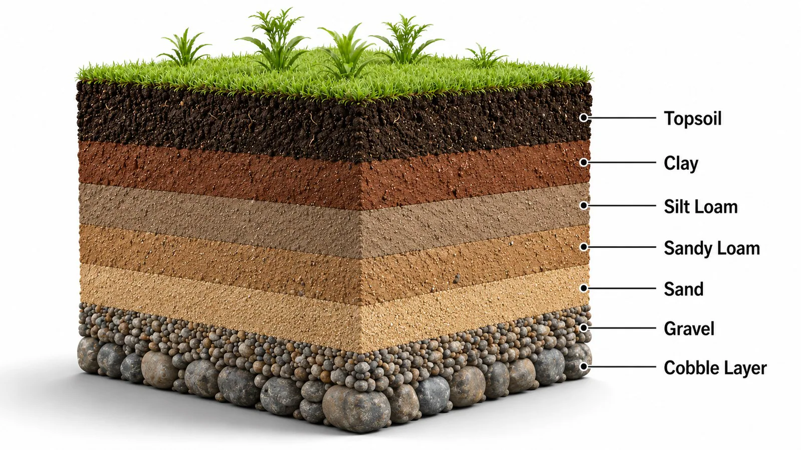
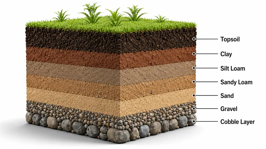
The soil illustrations show material categories and a conceptual profile. They are not a project ground model, a measured sample record or a complete engineering classification.
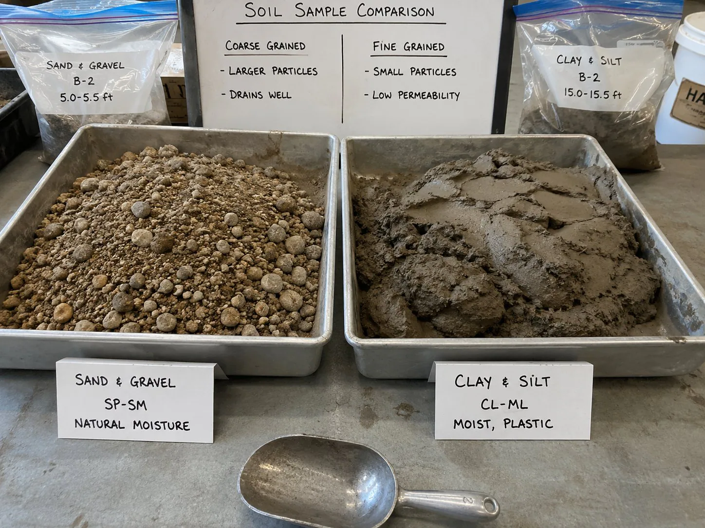
Illustrative comparison of coarse particles and moist fine-grained material. Appearance alone does not establish the engineering classification or strength; use project samples and test results.
Ground review
Assess the properties of each layer
Use these material groups to organize the investigation review. Project test results and the specified engineering classification determine how you describe the ground.
Soil groups and installation checks
01
Organic soil / topsoil
PropertiesCompressibility, organic content and variable near-surface conditions
InvestigationSamples, organic content and settlement assessment
Planning checksAssess support, settlement and downdrag; design the working platform for equipment loads.
02
Clay
PropertiesStrength, sensitivity, plasticity, drainage and time effects
InvestigationSamples, water content, plasticity, strength and interpreted field tests
Planning checksReview remolding, pore pressure, heave, ground movement and the time basis for acceptance.
03
Silt / mixed fines
PropertiesPlasticity and drainage can change the response
InvestigationGrading, plasticity, groundwater and field-test interpretation
Planning checksUse the measured properties; a silt or loam description does not select a driving method.
04
Sand
PropertiesDensity, stress level, saturation and cementation
InvestigationInterpreted SPT or CPT, grading, groundwater and layer thickness
Planning checksReview driveability and cyclic ground response with vibration and settlement limits.
05
Gravel
PropertiesParticle size, grading and variable penetration resistance
InvestigationRecovery, grading, probing and the context of refusal
Planning checksAssess toe blockage, pile damage, test limitations and approved contingency methods.
06
Cobbles, boulders / debris
PropertiesDiscrete obstructions can block or deflect a pile
InvestigationBorehole and excavation records, probing where specified
Planning checksDefine stop conditions and obtain review before changing the pile or installation method.
07
Fill
PropertiesProperties depend on source, placement, compaction and inclusions
InvestigationPlacement records, samples, investigation and quality records
Planning checksAssess variability, settlement, buried objects and working-platform requirements.
Read investigation results with their limitations
Record
Information
Interpretation limit
Boring logs and samples
Material, layer depth, recovery and observation dates
Account for gaps between investigation points.
SPT
Penetration resistance with the field setup and required corrections
Coarse particles can distort results; very soft clay correlations have limitations.
CPT / CPTu
Cone resistance, sleeve friction and pore pressure where measured
Interpret soil behavior with samples; coarse particles or hard layers can stop the probe.
Laboratory tests
Grading, plasticity, water content and strength where specified
Use the applicable classification and test procedure.
Groundwater
Dated levels, pressure conditions and possible variation
Assess drainage, ground movement and water-control requirements.
Installation and testing
Depth, operating settings, penetration or blows, condition and specified tests
Apply the engineer’s acceptance procedure; penetration alone does not prove capacity.
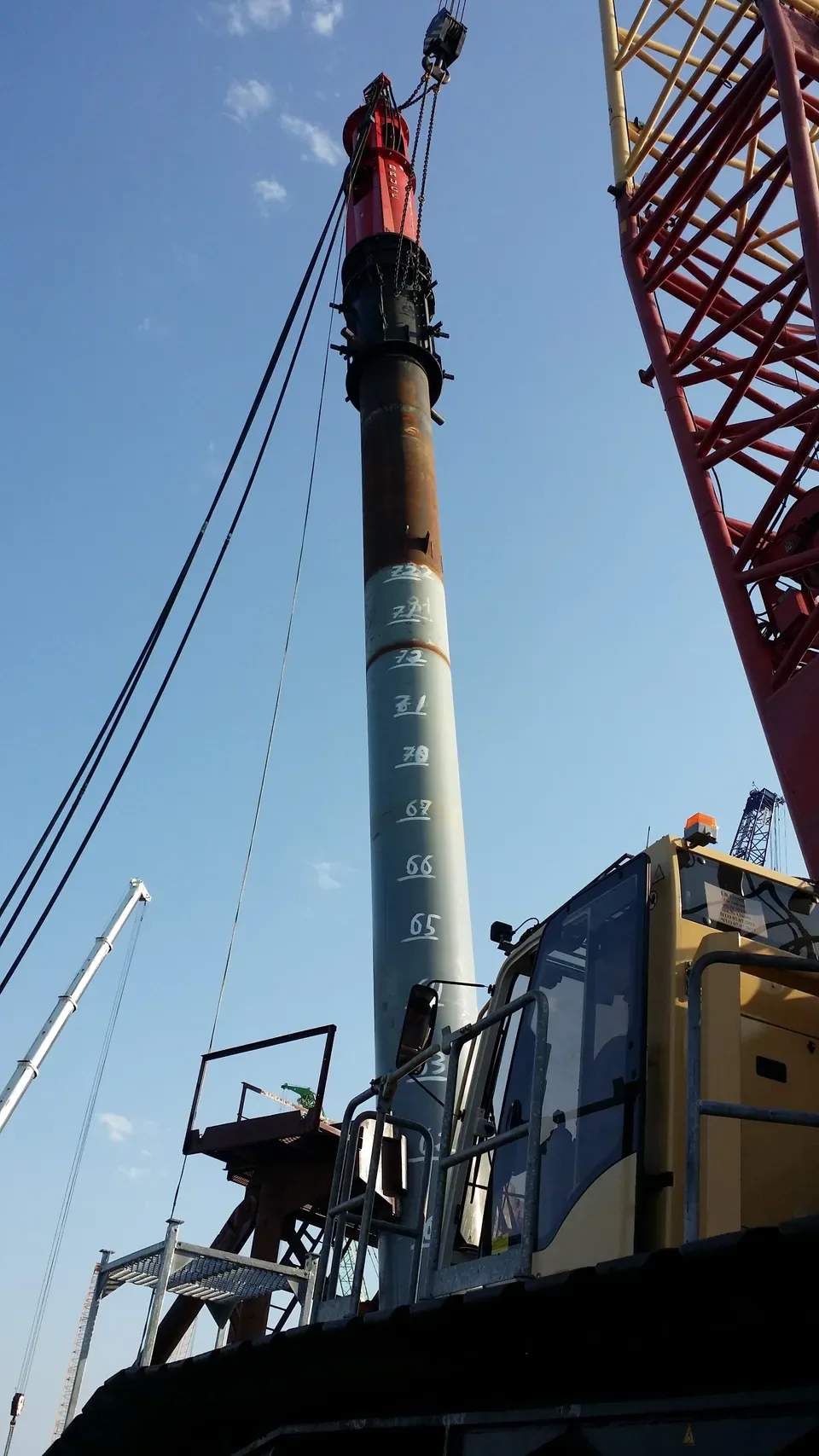
BRUCE equipment in the field
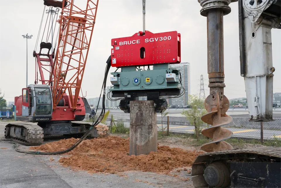
The photographs show visible equipment arrangements. They do not establish the site’s soil properties, equipment ratings or suitability for another project.
BRUCE SGV300 vibratory hammer with steel pile, crane, drilling equipment and hydraulic hoses visible.BRUCE hydraulic impact pile hammer positioned on a steel tubular pile beside a crane.
●Soil classification and driving behavior
Engineers classify soil from particle-size distribution, plasticity and other investigation results using the system specified for the project. Under the Unified Soil Classification System (USCS), sand and gravel are coarse-grained materials; fine-grained classifications depend on plasticity as well as particle size. Soil descriptions alone do not establish strength, density, stiffness or drainage.
Silt loam and sandy loam are USDA texture names. Use laboratory results and the project classification procedure to interpret those descriptions for engineering work. Two layers with the same soil name can require different installation methods because their density, stress history, cementation, groundwater and obstructions differ.
●Topsoil, organic layers and fill
Organic soils can be compressible and variable. The designer must assess their suitability for support and any settlement or downdrag effects on piles passing through them. Uncontrolled fill may contain soft pockets, debris or obstructions; the word fill does not establish its engineering properties.
The project team must also assess the working platform for the actual crane and equipment loads, drainage and construction sequence. A pile design does not establish that surface ground can support the installation equipment.
●Clay and silt
Fine-grained soil behavior depends on plasticity, strength, sensitivity, drainage and stress history. Driving in saturated clay can disturb the soil and generate excess pore pressure. Immediate driving resistance can differ from resistance after pore-pressure dissipation and other time effects. The engineer specifies any waiting periods, restrike observations or tests needed for acceptance.
Soft clay can permit penetration while the pile group or nearby ground moves. Stiff clay may present high resistance. Silt can have plastic or nonplastic behavior, so classify the material and assess its drainage response before using a sand-or-clay equipment rule.
●Sand, gravel and obstructions
Engineers assess sand using density, stress level, grading, cementation and groundwater information. Vibration can reduce pile-soil interface resistance in suitable ground, but dense or cemented layers can limit penetration. Saturated loose sand may develop excess pore pressure or densify under cyclic loading; assess possible settlement and effects on nearby structures. Gravel, cobbles, boulders and buried debris can block or deflect a pile and damage its toe or shaft.
Check the investigation coverage and define stop conditions before work. Probing, predrilling, jetting, a pile change or another method needs project approval where proposed. These measures can change the ground and pile resistance; additional hammer energy alone does not resolve an unknown obstruction.
●Ground investigation and its limits
Read borehole logs with the test methods, sample depths, recovery and quality notes. SPT N-values provide penetration-resistance information, but gravel or a local cobble can affect a result or cause refusal. Do not interpret one refusal as proof of a continuous bearing layer. SPT correlations also have limitations in very soft clay. Apply the corrections and interpretation required by the selected engineering procedure. CPT records cone resistance and sleeve friction; CPTu also measures pore pressure.
Engineers infer soil behavior from those measurements. A CPT behavior type is not a sampled USCS classification, and coarse particles or hard layers can limit penetration. Combine the profile with boreholes, samples and laboratory tests. Grain-size tests, Atterberg limits where applicable, strength tests and dated groundwater observations help assess the ground model. Record the uncertainty between investigation points and possible seasonal, tidal or artesian water conditions.
●Select and verify the installation method
Review vibratory driving for compatible piles where the ground response and site vibration limits permit it. For impact driving, review hammer operation, driving assembly and allowable pile stresses against the expected resistance. The pile drawing, depth, ground model, crane arrangement, hydraulic package and project specification determine the candidate equipment. A soil name does not select a BRUCE SGV or SGH model. The responsible engineer must review any combined sequence or penetration aid, including its effect on design assumptions.
Set monitoring locations, action limits and responses for nearby structures, utilities and other sensitive receptors where required. Keep installation records that identify pile depth, hammer settings, penetration or blow counts, interruptions, pile condition and the specified monitoring results. Penetration rate or final set alone does not establish service capacity. Review driveability before work and apply the project acceptance procedure, with restrike, dynamic testing or static load testing where specified.
●Project responsibility
The responsible project team approves the geotechnical and structural design, installation method, working platform, lifting plan, permits, monitoring and acceptance requirements. Confirm the manufacturer’s operating limits and instructions for the selected hammer, interface and hydraulic system. Stop and obtain the required review if the ground response, pile condition or monitoring results fall outside the approved limits.
QCan a soil name determine the pile-driving method?
Use the layer properties, groundwater, pile details and project requirements. Sand can be loose, dense, cemented or mixed with coarse particles; clay can vary in strength and sensitivity. Confirm the permitted method and candidate equipment with the responsible engineer and manufacturer.
QDoes a high SPT N-value prove a continuous bearing layer?
A result describes the tested interval under the reported test conditions. Gravel or a local cobble can affect the blow count or cause refusal. The geotechnical engineer must interpret the result with recovery, adjacent investigation points and the test quality and correction records.
QCan crews use predrilling or jetting if penetration slows?
Use an aid only under the approved project method. The designer must review its dimensions, depth, ground effects and implications for pile resistance and acceptance. Stop and obtain review if the encountered conditions or required changes exceed the approved limits.
QDoes reaching the target depth confirm pile capacity?
Apply the specified acceptance procedure. Depth, penetration rate or final set alone does not establish service capacity. The responsible engineer defines the installation records, waiting or restrike requirements and tests needed for the project.