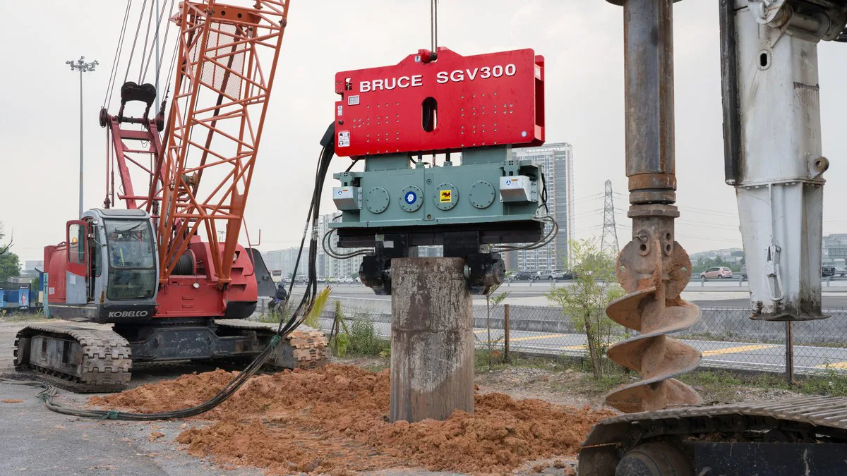
BRUCE SGV300 vibratory hammer on a steel pipe beside a crawler crane and auger

Knowledge CenterPile Types

Pipe Pile Guide

Two steel pipes with the same outside diameter can behave differently during driving. An open toe lets soil enter. A closed toe blocks entry through the base and displaces soil as the pipe advances. The wall thickness, ground profile and way the hammer engages the pipe also affect installation.

Compare pile and toe details

Direct answer

What is a steel pipe pile?

A steel pipe pile is a tubular foundation member. Under axial compression, it can transfer load to the ground along its outer wall and at its toe. With an open toe, soil inside the pipe can also contribute to resistance. The designer checks the pile for the loads it will carry, including uplift and lateral loads where they apply.

Last updated
Prepared byBRUCE Technical Team
ScopeDriven steel pipe piles

Pipe and site details to check before driving

Steel pipe pile installation checks
Planning item Requirement to review Installation checks
Pipe section The outside diameter and wall thickness determine the steel cross section. A pipe can arrive out of round or suffer damage during handling. Compare the delivered pipe, steel grade and dimensions with the drawing. Check the head for dents before attaching the hammer.
Toe detail An open pipe admits soil. A closure plate excludes soil at the toe. An open cutting shoe can reinforce the rim while leaving the pipe open. Confirm the detail on the fabrication drawing and inspect it before driving. Check whether the design allows soil to be removed from inside the pipe.
Ground profile Loose fill may overlie dense material, or rock may slope across the pile locations. Resistance can change with depth. Match the pile location to the investigation. Agree on the driving criteria and what the crew should do if the pipe stops short or moves out of alignment.
Hammer interface A vibratory hammer grips the pipe with a clamp. An impact hammer transmits blows through a driving head or helmet. Check the clamp contact or driving-head fit against the pipe drawing. Review the proposed hammer, guides and crane arrangement for the planned sequence.
Service exposure A pipe at a waterfront may have sections in air, in the splash or tidal zone, under water and below the bed. Use the corrosion provisions in the design. Inspect coating damage and complete the specified repairs at welds, handling points and the pile head.

References: 1, 2, 3

01

What happens inside an open-ended pile?

As the pipe advances, soil can rise inside it. If the soil keeps entering, the steel ring at the toe bears on the ground and friction develops along the inside wall. If enough resistance develops between the soil and the wall, the soil column may start moving down with the pipe. Engineers call this plugging. The pile can pass through intermediate stages as driving conditions change.

A closed toe displaces soil across the full cross section. An open pipe driving in an unplugged condition usually displaces less soil than a closed pipe of the same diameter. An open pipe that plugs can behave more like a closed one during driving.

The plug can behave differently under a hammer blow and under a sustained foundation load. The geotechnical designer selects an appropriate resistance model for each condition. If the design depends on soil inside the pipe, agree on any cleanout before removing it.
References: 1, 3

02

Pipe dimensions, splices and infill

Two pipes of the same diameter can have different wall thicknesses and steel grades. The designer checks the section for handling, driving and service. For a marine pile, scour can lower the bed and increase the unsupported length. That matters when checking bending under lateral loads.

A splice must carry the forces specified for the pile and withstand installation. Follow the joint detail and welding procedure, keep the pipe sections aligned and complete the required inspection. A damaged head or a splice that sits out of line needs attention before the next driving run.

Some designs leave the pipe hollow. Others call for a partial or full concrete fill, reinforcement or a connection to a pile cap. Use the drawings to establish the extent of fill, the required preparation inside the pipe and the connection detail.

References: 1, 2, 3

03

Choose the driving method and fit the pile head

Vibratory installation is an option for compatible pipe sections and ground conditions. Check that the clamp fits the actual diameter, wall and head condition. The supplier needs the pipe drawing to check jaw contact and clearance. Include hydraulic flow and pressure, the suspended equipment weight and the crane’s working radius in the equipment review.

For impact driving, check that the driving head fits the pipe and transfers the blows in line with its axis. Use the cushion arrangement specified for the hammer and pile. A wave equation analysis can estimate pile stresses and blow counts for the proposed hammer and assumed soil resistance.

Some projects start with vibration and finish with impact. Agree in advance on where or under what conditions to change methods and how the finished pile will be accepted. A sudden stop, unusual head deformation or loss of alignment calls for a review of the pile, equipment and ground before anyone increases the hammer setting.

References: 2, 3

04

Read the installation record against the driving criteria

Record the pile location and identification, section lengths, toe detail, hammer and dates. For impact driving, record blows over the specified penetration interval and the hammer stroke or energy setting. For a vibratory run, record depth against time and the equipment settings. Note splices, interruptions and any change of method.

For an open pile, the project may also require measurements of the soil level inside the pipe. Record those measurements with the pile penetration and any material removed. A single internal soil level cannot establish how much axial load the completed pile will carry.

A high blow count can reflect hard ground, a local obstruction or a change in hammer performance. The engineer compares the driving record with the project criteria and calls for restrike, dynamic measurements or a static load test where the specification requires them.

References: 1, 2, 3

05

Permanent piles and temporary casing

A round steel pipe can be a permanent foundation pile or a casing that supports a bore during construction. The drawings identify its purpose, whether it stays in the ground and whether it contributes to the completed foundation.

For a permanent pile, the designer specifies corrosion protection for the exposure and service life. Options include extra steel thickness, a coating or cathodic protection where appropriate. Record the installed cutoff elevation, connection and any repairs the specification requires.

For temporary casing, check the removal sequence and expected ground resistance. An embedded pipe can require a greater pull than its own weight. The lifting team and equipment supplier must account for the proposed extraction forces, clamp limits and crane configuration.

References: 1, 2, 4

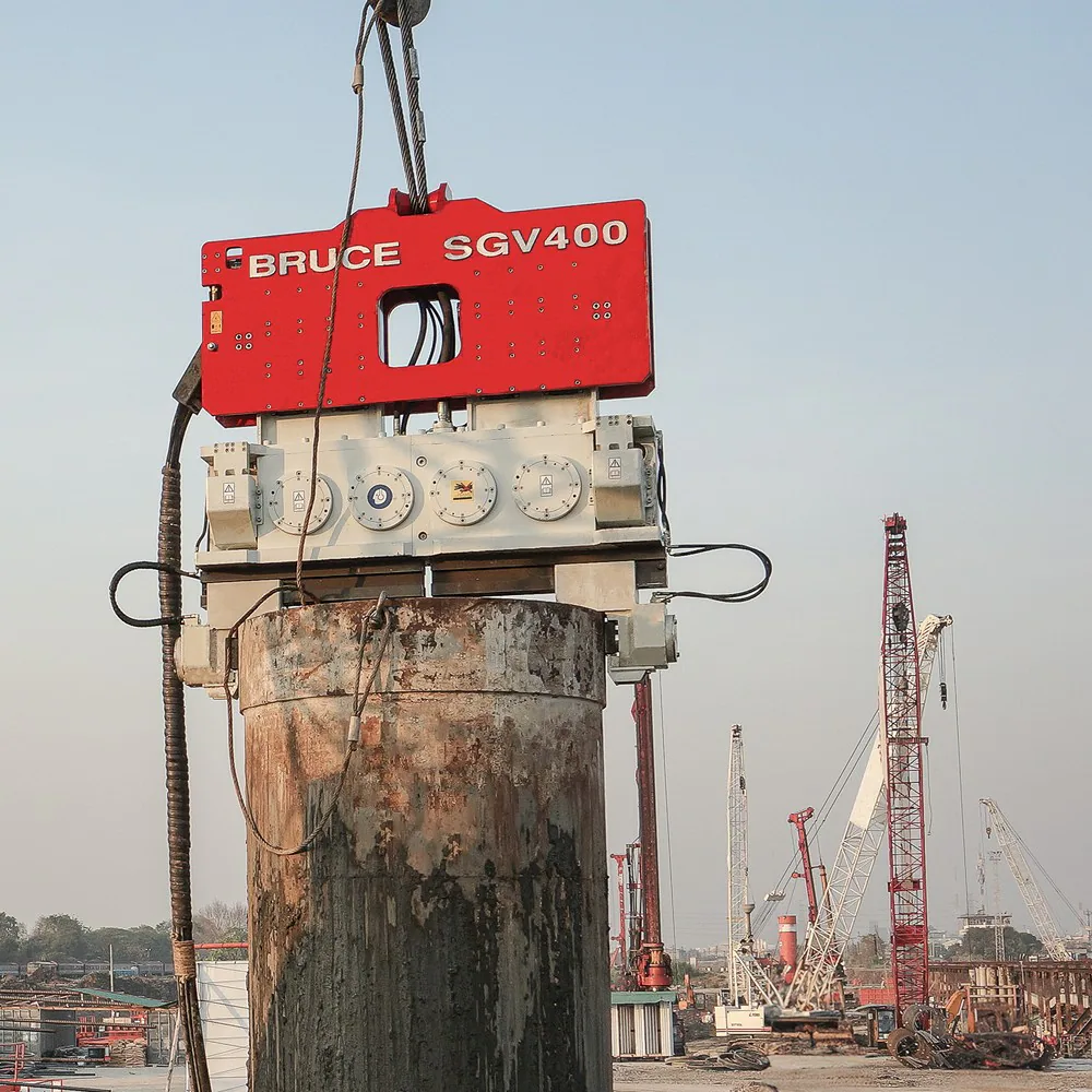
BRUCE SGV400 vibratory hammer and clamp at the head of a steel pipe
The clamp on this BRUCE SGV400 grips the head of a steel pipe.

Equipment review

Discuss equipment for your pipe pile

Send the pipe drawing and ground information you have. The BRUCE Technical Team can check the proposed hammer and its attachment against your pipe dimensions.

Discuss your project

Frequently asked questions

Does a pipe pile with a driving shoe have a closed end?

Check the toe drawing. A cutting shoe can protect the rim of an open pipe and still allow soil to enter. A welded closure plate or a specified closed point seals the toe.

Can the crew remove soil from an open-ended pipe before concreting?

Follow the approved cleanout and fill detail. If the design relies on the internal soil for resistance, the engineer must check the effect of removing it and define the permitted depth.

Is the outside diameter enough to select a vibratory clamp?

The supplier also needs the wall thickness, tolerances and condition of the pile head. Check the clamp drawing for jaw contact, clearance and rated limits for the planned installation or extraction.

What should the crew record if a pipe pile stops above its target depth?

Note the depth, penetration trend, hammer settings and condition of the visible pipe and driving head. Notify the responsible engineer and follow the project’s stop criteria. An unexpected stop alone does not identify the bearing layer or prove capacity.